
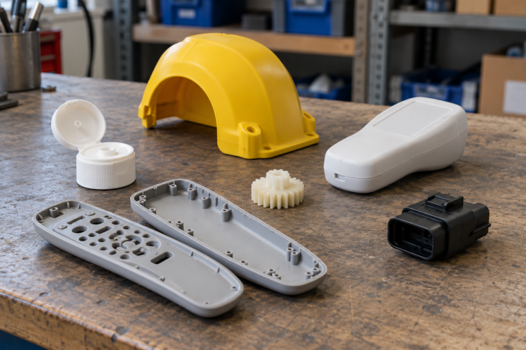
Injection molding makes plastic parts by pushing melted plastic into a shaped metal mold. The plastic cools until it holds its shape, then the mold opens and releases the part. The same mold repeats this cycle to make more parts.
The products range from bottle caps, food-storage boxes and remote-control housings to robot covers, plastic gears, electrical connector bodies and medical-device enclosures. The process serves both everyday products and demanding applications. The difference lies in the design, material grade, tooling and production controls; a medical enclosure or electrical insulating component needs requirements that an ordinary household cover may not.
This article focuses on thermoplastic injection molding: plastic is softened by heat and becomes solid again as it cools. We will follow a simple remote-control housing from its design to the finished part.
Before production: how the mold is designed and made
A mold is a reusable metal tool with a space shaped like the part. For a hollow remote-control housing, a recessed side forms the outside, while a raised side forms the inside. Closing these two sides leaves a thin space between them for the plastic. The machine supplies heat, movement and pressure; the mold supplies the shape.
Start with the part design
The customer usually supplies a 3D CAD model, a digital model of the part, plus any drawings and requirements for material, quantity, appearance and fit. If the idea is only a sketch, product design may be a separate step before tooling can begin.
An engineer then checks whether the part can fill, cool and come out of a mold. This is called design for manufacturability, or DFM. For our housing, the review might reduce a thick area, adjust an internal reinforcing rib or add a slight wall taper so the part releases more easily. Changes should be agreed before metal is cut.
Design the tool around the part
The mold designer plans where its sections meet, where plastic enters, how trapped air escapes, where cooling passages run and how the part will be pushed out. The design also allows for plastic shrinkage. A side-facing hole or hook may need a moving section, making the tool more complex. Flow simulation can help assess difficult filling or cooling problems when the project calls for it.
Cut and assemble the metal
Molds commonly use tool steel or aluminum. P20-type prehardened steel is one common option; hardened tool steels may suit more demanding production, while corrosion-resistant steels can help where the resin or operating conditions call for them. Aluminum is often considered for prototypes and shorter runs. There is no universal best mold metal: expected life, resin, finish, maintenance and cost all affect the choice.
Yes, CNC machining is a major part of moldmaking. Computer-controlled milling removes metal to form the main shapes, pockets and other features. Electrical discharge machining, or EDM, uses controlled electrical sparks to erode conductive metal and can help make deep details or shapes that are difficult for a milling cutter to reach. Drilling creates passages and holes; grinding, polishing or texturing finishes the required surfaces. Heat treatment is added when the selected steel and tooling plan require it, with the machining sequence arranged accordingly.
The toolmaker assembles the inserts, mold base, cooling connections and release mechanisms, then runs molding trials. Sample parts are checked for fit, dimensions, appearance and defects; adjustments may follow before production is approved. Typical project support therefore spans part review, mold design, manufacture, trials and agreed corrections. Confirm which tasks and deliverables are included when requesting a quote.
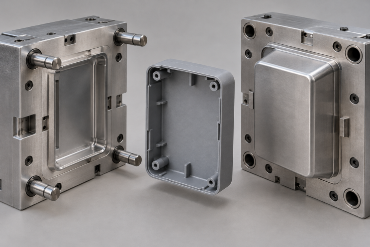
Simplified illustration of a mold cavity, core, and hollow plastic housing.
How plastic pellets become a finished part
The finished mold is installed in a compatible injection molding machine. Think of the machine as a heated plastic feeder joined to a powerful clamp. Its main parts are a hopper that holds pellets, a heated barrel containing a screw, and the mold held between the clamp plates.
1. Prepare and melt the plastic
Pellets fall from the hopper into the heated barrel. Materials that absorb moisture may need drying first. For our remote housing, the selected plastic must be prepared according to its grade’s processing instructions.
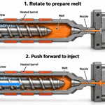
Inside the barrel, a screw rotates and carries the pellets forward. Heaters around the barrel and the screw working the material together produce the heat needed to form a melt. A measured amount of melted plastic collects in front of the screw, ready for the next part.
The screw has two jobs at different times: it rotates to prepare the plastic, then moves forward like a plunger to inject it. It does not simply spin the plastic into the mold.
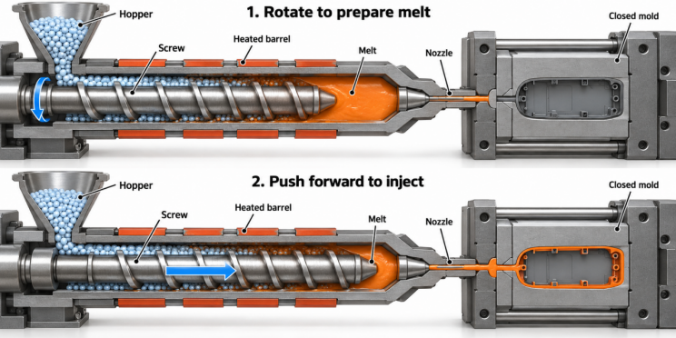
Simplified cutaway: the screw rotates to prepare melt, then moves forward to inject it.
2. Close the mold and fill its part-shaped space
The clamp holds the mold shut. The screw moves forward, pushing the melt through the nozzle and the mold’s feed path into the empty space shaped like our housing. That space is called the cavity. Small vents let displaced air escape.
The machine must keep the mold closed against the pressure of the incoming plastic. A tool may have several cavities, so one cycle can produce several matching parts.
3. Hold pressure, then let the part become firm
Plastic usually shrinks as it cools. Immediately after filling, the machine keeps pressure on the melt to feed a little more material into the part while the small entry point, called the gate, remains able to pass melt. This is the holding or packing stage. It helps compensate for shrinkage; it does not continue adding material after the gate freezes.
Cooling passages in the metal tool carry water or another temperature-control fluid. The fluid removes heat through the mold wall; it does not flow into the plastic part. Cooling already starts when the melt touches the tool and continues until the housing is firm enough to be removed without losing its shape.
4. Open the mold and release the part
The clamp separates the mold halves. Small metal rods called ejector pins, or another release mechanism, push the solid housing off the tool. A robot or operator may then take it away. Any attached feed-path plastic is separated where needed; some tool designs avoid a separate runner attached to the part.
The mold closes again. The screw can prepare the next amount of melt while the previous part is cooling, so some actions overlap. Material, wall thickness, tooling and settings determine the cycle time.
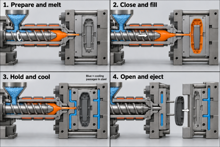
Four learning stages shown separately; some machine actions overlap in production.
What the mold controls
The mold gives the part its basic shape, many of its surface details, and a path for release. In a plastic housing, one side of the tool may form the outer surface while another forms the hollow interior, ribs, and screw supports.
The mold surface can be polished or textured, allowing the plastic to pick up a smooth, matte, or patterned finish during molding.
The tool also leaves clues about how the part was made. A fine line may mark where mold sections meet. A small mark may show where plastic entered. Ejector pins can leave marks where they pushed against the part.
Release affects the design, too. Walls often have a slight taper, called draft, so the part can slide out more easily. A side-facing hole or a hooked feature may need moving sections in the mold, adding complexity.
The mold works together with the plastic and machine settings. Changes in material shrinkage, temperature, or pressure can affect dimensions even when the same tool is used.
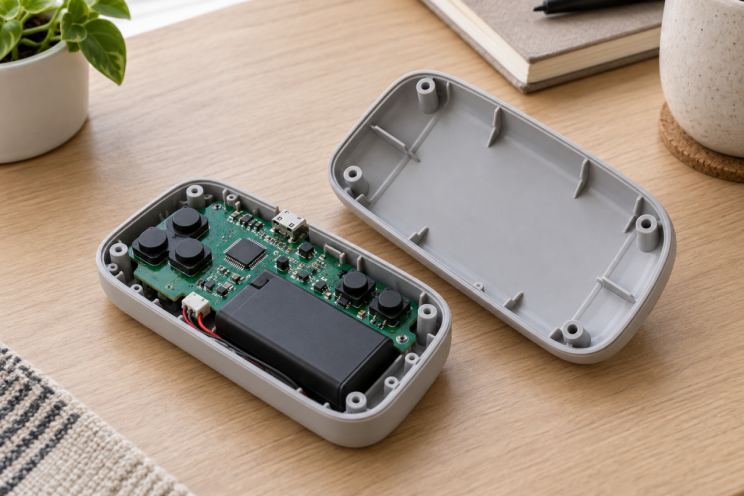
Which plastics and products use injection molding?
The right plastic depends on the job. A flexible bottle cap, a clear guard and an electrical connector need different properties. The following common choices give a useful starting point; the exact grade still matters.
| Plastic | Familiar molded applications | Why it may be selected |
| Polypropylene (PP) | Caps, containers and suitable hinged closures | Low weight and flexibility; appropriate grades withstand repeated hinge movement |
| ABS | Remote controls, appliance housings and robot covers | A useful balance of rigidity, impact resistance and surface appearance |
| Polyethylene (PE) | Closures, containers and some protective components | Toughness, flexibility and chemical resistance, depending on the grade |
| Polycarbonate (PC) | Clear protective covers and equipment components | Transparency and impact resistance; suitable grades also serve opaque housings |
| Nylon (PA6 or PA66) | Gears, clips and other working parts | Strength and wear performance; moisture absorption affects design and dimensions |
| Acetal (POM) | Small gears, sliding components and precision mechanisms | Low friction and dimensional performance suited to many moving parts |
| PC/ABS blend | Electronics and equipment enclosures | A balance of processing, impact and heat performance, depending on the formulation |
Other useful families include PS for certain rigid consumer parts, PMMA for clear parts where optical appearance matters, and PBT for many connector and electrical-component applications. Flexible thermoplastics such as TPE and TPU can form grips, soft-touch areas and suitable seals, including in some overmolded parts.
Higher-performance choices include PPS, PEEK, PEI, PPA and LCP. Depending on the family and grade, they can address higher temperatures, chemical exposure, dimensional demands or electrical requirements. They usually need more specialized processing and are not automatic upgrades for a simple housing.
A robot cover may prioritize impact and appearance, while an internal gear needs wear performance. A medical-device part may need compatibility with its cleaning or sterilization method; an electrical insulating part may need specified electrical and flame performance. Neither medical suitability nor electrical safety follows from a polymer name alone. The grade, design, testing and applicable product requirements must support the use.
Fillers and additives can change stiffness, shrinkage, appearance and other properties. Choose the material with the part’s actual environment and production process in mind, rather than selecting the longest material list or the highest price.
Why manufacturers repeat the process at scale
Injection molding can become economical when the cost of making the tool is spread across many parts. Once a stable process is established, the same mold can reproduce the part’s shape and surface over repeated cycles.
That advantage comes with an upfront commitment. The mold needs design work, manufacture, and trials before routine production. If the product changes later, the tool may need modification or replacement. A change that is simple in a drawing can require significant work in metal.
There is no single order quantity at which injection molding becomes the best choice. Part size, resin, mold complexity, cavity count, inspection, and expected demand all affect the economics. Short runs can still make sense when the project needs molded material behavior or repeated small orders.
Quality also depends on controlling the process. Incomplete filling, surface depressions, distortion, or excess plastic at mold joints can occur when the design, material, tool, and settings do not work well together.
When a design is still changing, another process may offer a simpler way to test it. The separate PlasticHubs guide to 3D printing vs injection molding explains that choice in more detail.
[FAQ insertion point: open 03_FAQ_Accordion_EN.docx and copy only the code between the BEGIN and END markers into a WordPress Custom HTML block or HTML widget. Do not copy the marker lines. Remove this instruction before publishing.]
Have a plastic part in mind? Contact PlasticHubs with your part idea, quantity, and material requirements to discuss the next step.
Questions people ask about injection molding
Is the mold the same thing as the injection molding machine?
The machine supplies the clamping force, heat, and injection movement. The mold is the tool fitted into it to form a particular part. A machine can run different compatible molds, provided its capacity and setup suit the job.
Do injection-molded parts need finishing?
Some parts can be used after removal and any necessary trimming. Others need painting, printing, joining, or additional work. The mold can create texture and surface detail, but the required appearance and function determine the remaining steps.
Can recycled plastic be used in injection molding?
Yes, when the recycled material is suitable for the application and can be processed consistently. Contamination, previous heat exposure, color variation, and changing properties can affect the result. The acceptable material and recycled content must meet the product’s requirements; there is no universal percentage for every part.
Is every plastic product injection molded?
Plastic products use several manufacturing processes. Blow molding commonly makes hollow bottles, extrusion makes continuous shapes such as pipe, and thermoforming shapes heated sheet. A bottle and its cap may therefore come from different processes, even though both are plastic.