Choose plastic CNC milling when the part needs:
- Flat or prismatic geometry
- Pockets, ribs and mounting features
- Several controlled faces
- Tool-free prototypes or low volume
- Machined engineering-plastic stock
- Critical feature inspection

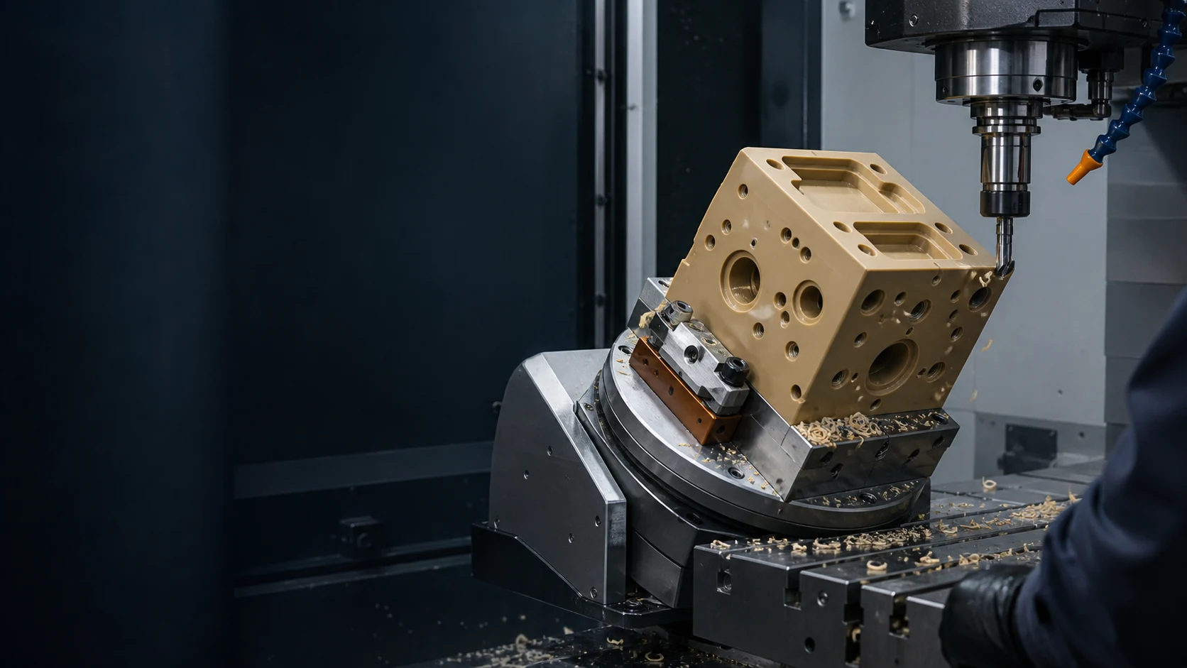
Custom-milled housings, plates, fixtures, manifolds and multi-face components—reviewed around material behavior, tool access, workholding, critical features and inspection needs.
Send a 3D CAD model, drawing, material or performance target, quantity, finish and critical requirements.
Milling is strongest when the part is cut from solid stock and its functional geometry is defined by faces, pockets, profiles, holes, slots or multi-side relationships.
Bushings, rollers, sleeves and rings may belong on a turning route.
Review plastic CNC turning →Use the parent page when milling, turning and multi-axis routes are still undecided.
Review plastic CNC machining services →Compare tooling economics and design maturity before assuming machining is the lowest-cost route.
Ask for a manufacturing review →Capacity is useful only when it is connected to the plastic grade, geometry, setup plan, and inspection method. These figures define the available route before part-specific review.
Final capability depends on material, feature size, wall stiffness, tool access, workholding, residual stress, finish, and measurement state.
Axis count is not a quality badge. The correct route minimizes risky setups while preserving tool access, datum relationships and inspection clarity.
Efficient for plates, brackets, panels, housings and accessible cavities.
Useful when side holes, angled interfaces or datum relationships must stay coordinated.
Consider coordinated or indexed 5-axis work when several directions or deep access dominate.
Switch between common feature types. The animated path is illustrative; the useful output is the setup and DFM questions that change with the geometry.
Tool reach, corner radius, floor thickness and chip recutting must be reviewed together.
The production route is confirmed only after PlasticHubs reviews the CAD model, material and critical features.
Exact grade, stock form, moisture, residual stress, temperature, chemical exposure, wear and appearance requirements matter more than a generic material name.
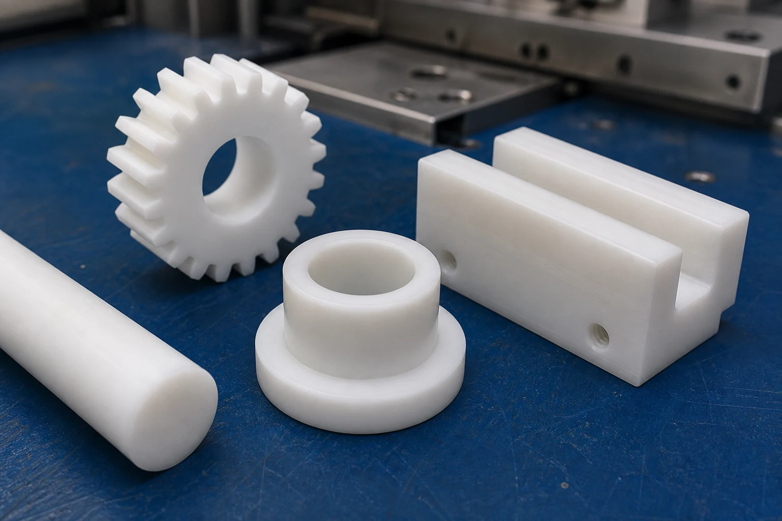
A strong candidate for dimensional stability, stiffness, low friction and clean mechanical features.
Plastic responds differently from metal. Workholding, tool access, heat, chip evacuation, residual stress and measurement state must be planned together.
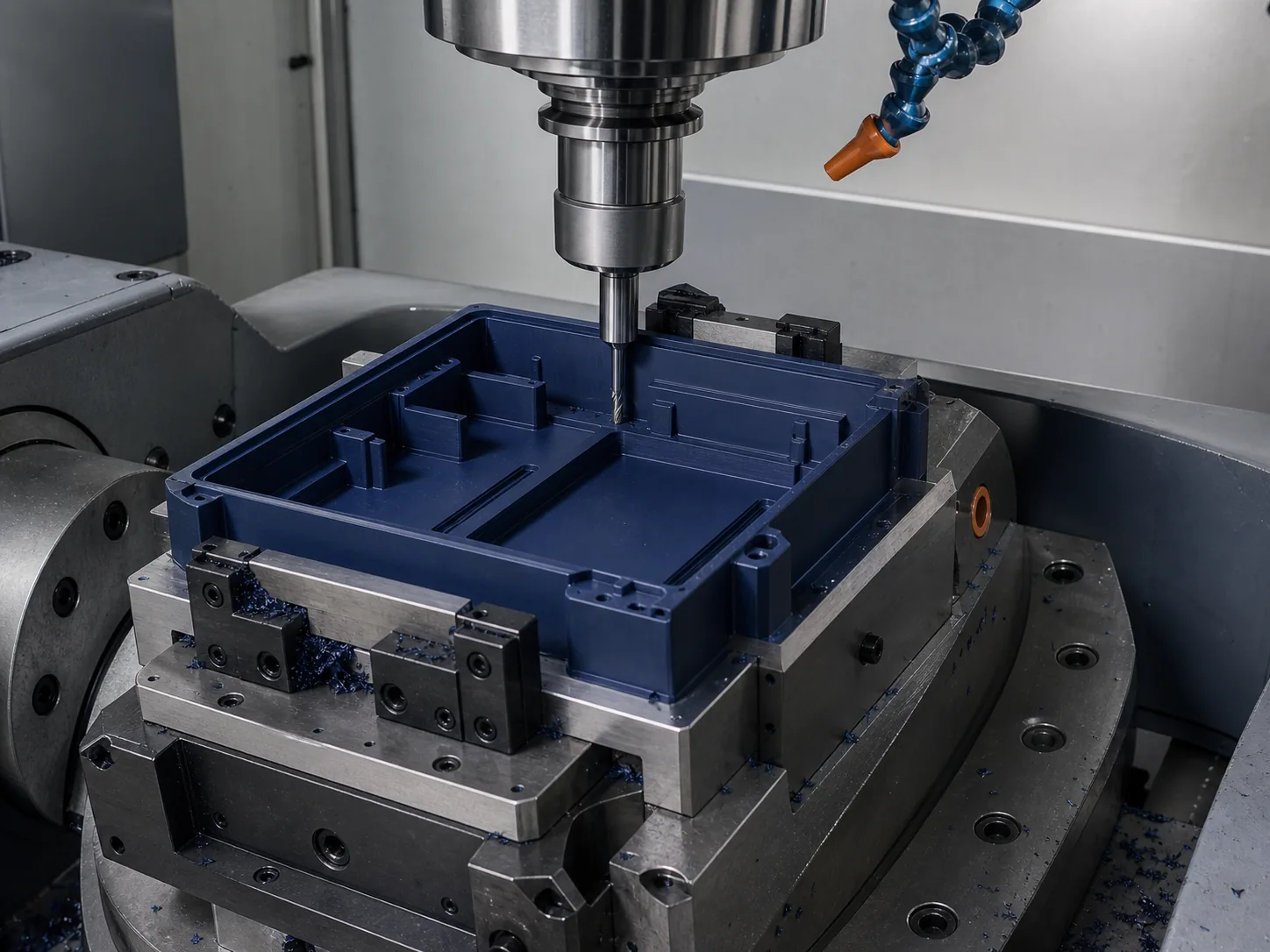
The correct process is selected from geometry, stock form, feature access, stiffness, quantity and inspection—not from the process name alone.
Best starting point for prismatic parts, pockets, faces, contours and controlled multi-side features.
Often considered for larger sheet parts, profiles, panels and nested flat components.
Usually preferred when the part is fundamentally cylindrical and most features reference a rotational axis.
The drawing should distinguish functional dimensions from general dimensions so measurement effort supports fit, motion, sealing and assembly.
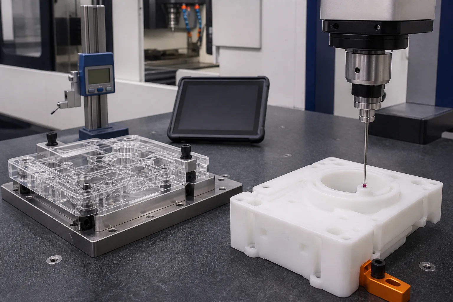
Complete inputs reduce avoidable clarification loops and keep material, geometry, inspection and appearance decisions tied to the accepted revision.
3D CAD plus a 2D drawing when critical dimensions, tolerances, threads or surfaces apply.
Give the exact grade or the functional requirements the material must meet.
Check access, walls, pockets, internal corners, datums, setup count and workholding.
Quantity, finish, inspection, appearance, packaging, delivery region and exceptions.
Return the proposed milling approach and open questions without unsupported universal promises.
Milling supports varied part families when the chosen material, stock, setup and acceptance criteria match the intended use.
Open enclosures, instrument bodies, equipment covers and controlled interfaces.
Ported blocks, distribution plates, mounting plates and fluid-control components.
Inspection nests, assembly aids, soft jaws, locating blocks and production tooling.
Structural supports, sensor mounts, adapters and equipment interfaces.
PMMA or polycarbonate windows, guards, covers and appearance-sensitive parts.
Guides, pads and contact parts where friction, wear and environment govern material choice.
Fit checks, functional trials and design validation without dedicated mold tooling.
Controlled revisions, datums, fixtures and inspection requirements for recurring demand.
Direct answers to material, tolerance, process, volume and quotation questions.
POM, PEEK, nylon, ABS, PTFE, PMMA, polycarbonate, PEI and other machinable stock plastics may be reviewed. Suitability depends on exact grade, geometry, stock form, temperature, chemicals, wear, moisture, appearance and critical dimensions.
There is no universal value for every plastic part. Material, feature size, wall thickness, workholding, heat, moisture, residual stress, finishing and measurement condition all affect the result. Identify the critical dimensions and their functional reason on the drawing.
Choose milling for flat, prismatic, pocketed, contoured or multi-face parts. Choose turning when the part is primarily cylindrical or rotational. Some parts may need both routes.
Yes. It can support one-off validation parts, low-volume production and repeat orders when material, revision, datum, fixture, finish and inspection requirements are controlled.
Cost is driven by material and stock, part size, removed volume, setup count, axis choice, tool access, feature complexity, quantity, finish, inspection and packaging. A file review is required for a useful quote.
Provide a STEP, STP or another usable 3D CAD model, plus a PDF, DWG or DXF drawing when critical dimensions, tolerances, threads or appearance requirements apply. Include material, quantity, finish, inspection needs, delivery region and intended use.
PlasticHubs will review the files, identify material and milling risks that need clarification, and define a project-specific manufacturing and inspection scope.