Choose plastic CNC turning when the part needs:
- Round or rotational geometry
- Controlled OD and bore relationships
- Bushings, sleeves or rings
- Rollers, spacers or valve seats
- External or internal threads
- Prototype to repeat production

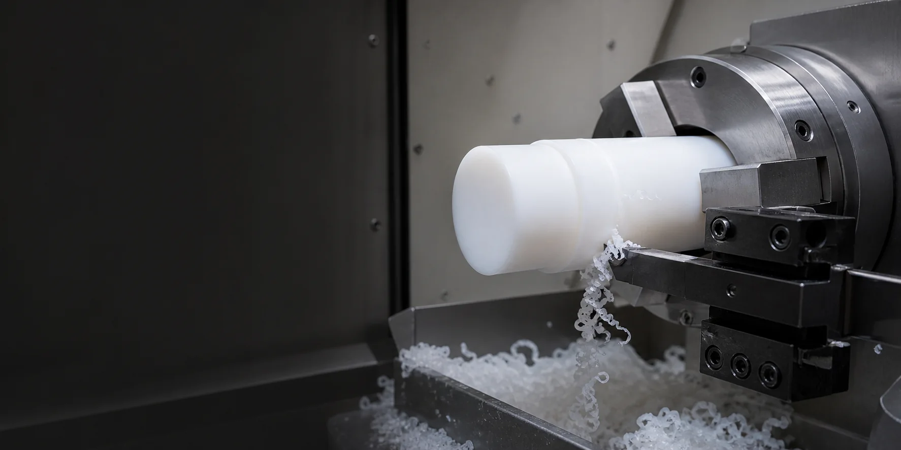
Custom bushings, sleeves, rollers, rings, spacers, valve seats and threaded plastic components—reviewed around material behavior, diameter relationships, wall support, workholding and inspection.
Send a 3D CAD model, 2D drawing, material or performance target, quantity, finish and critical requirements.
Turning is strongest when most functional geometry references one rotational axis and critical relationships involve outside diameters, bores, shoulders, grooves, threads or concentric features.
Pockets, faces, plates and multi-side housings usually belong on a milling route.
Review plastic CNC milling →Live tooling, mill-turn or a planned secondary setup may be required.
Explore turning features →Use the parent page to compare milling, turning and multi-axis routes.
Review plastic CNC machining →Published limits are screening values, not universal promises. Final feasibility depends on material, geometry, feature length, wall thickness, workholding, tool access and inspection method.
Use these values to start a conversation. Critical dimensions and edge cases remain subject to engineering review against the complete part.
This interaction links common rotational features to the process questions that should be resolved before quotation.
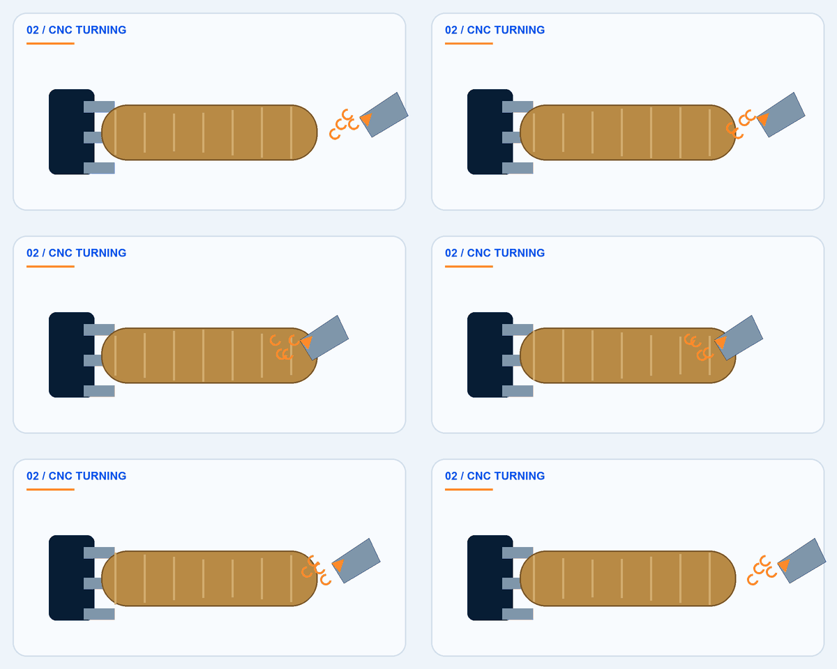
Outside diameters are reviewed with feature length, stiffness, tool access and the datum used for inspection.
Each selection changes both the image and the engineering notes. Grade, stock form, moisture, residual stress, temperature, chemicals, friction and appearance remain project inputs.
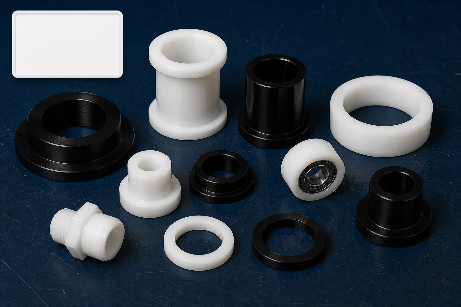
A strong starting point for stable diameters, low friction and clean mechanical features.
Plastic moves under jaw pressure, cutting force, temperature and released internal stress. Turning decisions must link geometry, stock, tooling, support and measurement condition.
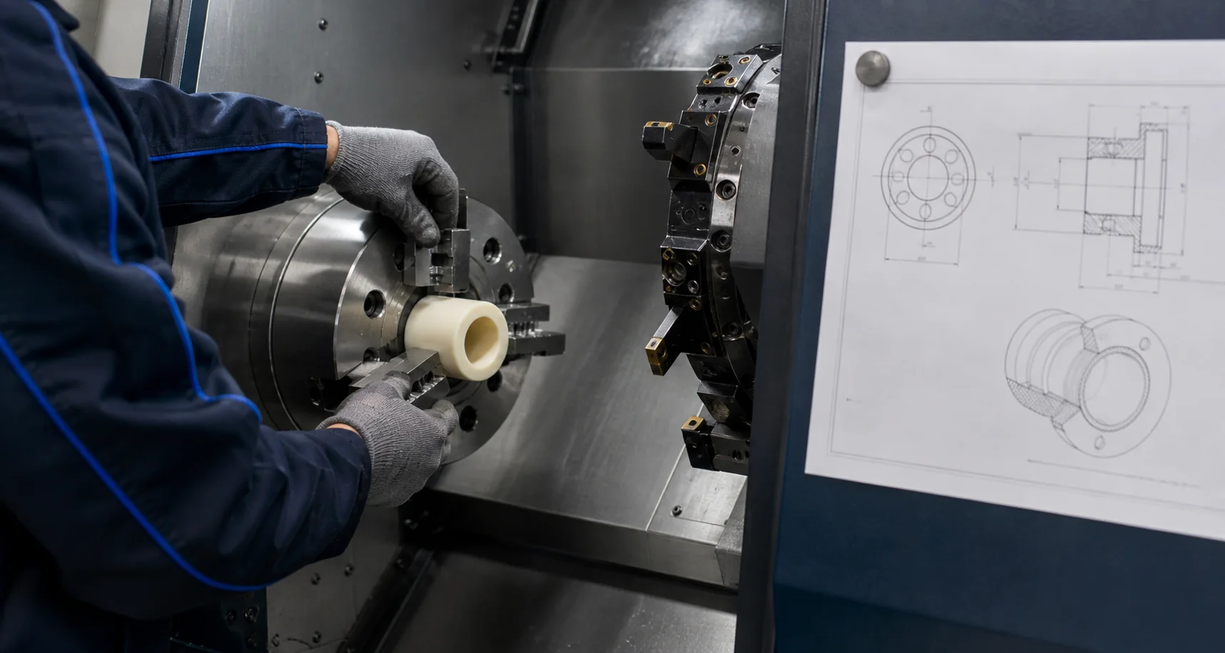
The preferred route is selected from the feature relationships, stock form, access, stiffness, quantity and inspection plan.
Best starting point when rotational geometry controls the part.
Useful when a rotational part also needs selected non-round features.
Usually preferred when faces, pockets and prismatic geometry govern.
Diameter alone is not the whole part. The drawing should identify the functional reason for bore, face, thread, runout and appearance requirements.
The measurement method and accepted condition are selected from the feature, material, tolerance and service requirement.
Complete inputs keep material, diameter relationships, workholding, inspection and appearance tied to the accepted revision.
3D CAD plus a 2D drawing for diameters, bores, threads, runout or critical surfaces.
Give the exact grade or the functional requirements the material must meet.
Check wall support, length-to-diameter, jaw contact, access and setup relationships.
Quantity, finish, inspection, appearance, packaging, delivery region and exceptions.
Return the proposed turning or mill-turn approach and the remaining engineering questions.
These families are starting points. Material, grade, geometry, volume and acceptance criteria still determine the final route.
Flanged, plain and precision-fit components for sliding or rotating contact.
Insulating sleeves, stand-offs, distance rings and cylindrical interfaces.
Conveyor, wear, film-handling and low-friction rotational components.
Guide rings, backup rings, seats and sealing-related geometries.
Seats, plugs, stems, nozzles and chemical-service flow-control parts.
Adapters, connectors, retainers and custom internal or external threads.
PMMA or polycarbonate sight components with separately defined appearance scope.
Controlled material, revision, workholding and inspection for recurring demand.
Direct answers to process, material, tolerance, volume and quotation questions.
Turning is a strong starting point for rotational parts such as bushings, sleeves, rollers, rings, spacers, valve seats and threaded fittings. Parts dominated by faces, pockets or prismatic geometry may belong on a milling route.
There is no universal value for every polymer and feature. PlasticHubs states a minimum turning tolerance of ±0.005 mm for suitable features, but actual capability depends on material, diameter, feature length, wall thickness, workholding, heat, moisture, stress and measurement conditions.
POM, PEEK, PEI, nylon, PMMA, polycarbonate, PTFE, UHMWPE and other machinable plastic stock may be reviewed. The exact grade, stock form and service requirements determine suitability.
Yes. Live tooling or a planned secondary milling operation may add flats, slots, cross holes and other non-rotational features when geometry and tolerance relationships justify it.
Yes. It can support one-off validation parts, low-volume production and repeat orders when material, revision, workholding, datums, finish and inspection scope are controlled.
Provide a STEP, STP or another usable 3D model plus a PDF, DWG or DXF drawing when diameters, bores, threads, runout, tolerances or appearance requirements apply. Include material, quantity, finish, inspection needs, delivery region and intended use.
PlasticHubs will review the files, identify material and turning risks that need clarification, and define a project-specific manufacturing and inspection scope.