A part that looks production-ready may not reproduce the material behavior, shrinkage, fatigue response, or dimensional stability of the final molded product. Vacuum casting can supply a small batch of polyurethane replicas with relatively low soft-tool commitment, while injection molding can test the target thermoplastic and some molding behavior. The engineering decision is therefore not which process has the lowest quoted unit price, but which process provides the evidence required at the current product stage.
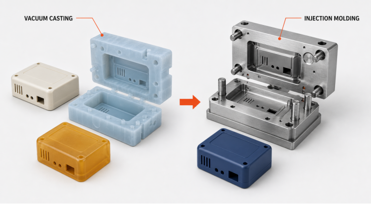
Vacuum Casting vs Injection Molding at a Glance
| Decision condition | Vacuum casting | Injection molding |
| Primary purpose | Appearance, assembly, ergonomic evaluation, display units, short-term functional tests, and bridge batches | Actual thermoplastic validation, repeat production of a stable design, and process confirmation when the tooling and molding conditions are representative |
| Tool | Flexible silicone mold made from a master pattern | Rigid aluminum or steel mold |
| Common material route | Polyurethane casting resin selected for properties such as ABS-like, PC-like, or PP-like behavior | Specified thermoplastic grades, including filled, flame-retardant, or otherwise modified systems |
| Material evidence | Can approximate selected attributes but is not automatically equivalent to the target thermoplastic | Can evaluate the specified resin grade, molding shrinkage, flow, surface, and as-molded performance |
| Design changes | Replacing a soft mold is usually less costly and easier to schedule | Tool changes may require welding, machining, inserts, or a replacement tool |
| Consistency limits | Master quality, silicone condition, casting, cure, demolding, and finishing | Tool condition, material lot, process window, packing, cooling, and process control |
| Cost behavior | Lower soft-tool commitment, followed by labor, cure time, and replacement-mold costs | Higher tooling commitment that can be spread across sustained demand after the design stabilizes |
| Main decision risk | Treating “ABS-like” as ABS or ignoring silicone-mold wear | Cutting metal before the design, wall strategy, draft, gate, ejection, and shrinkage plan are stable |
There is no universal quantity breakpoint. Part size, cavity count, side actions, cosmetic requirements, resin price, inspection scope, delivery pattern, and the probability of a design change can move the crossover in either direction.
Start with the Evidence the Test Must Produce
Appearance, assembly, and user evaluation
Vacuum casting is often suitable for color, texture, overall appearance, assembly space, and ergonomic evaluation. The resulting surface inherits the quality of the master, silicone mold, casting operation, and finishing, so surface quality is not independent of the chosen workflow.
Short-term functional testing
Polyurethane systems can be selected for target stiffness, hardness, clarity, flexibility, or thermal behavior, but the supplier’s datasheet must match the test conditions. A vague “ABS-like” or “PP-like” label is insufficient when the decision depends on sustained load, creep, fatigue, chemicals, UV exposure, flammability, or biocompatibility.
Production-material and molding-process validation
Injection molding provides more relevant evidence when the test depends on the specified thermoplastic grade, reinforcement, flame-retardant system, shrinkage, or melt-flow behavior. A polyurethane cast part cannot validate weld lines, gate effects, fiber orientation, molding shrinkage, or ejection behavior merely because its external geometry matches the molded design.
A low-volume injection tool does not automatically represent the final production process. Its data supports broader process confirmation only when tool material and cavity layout, gating, cooling, machine capability, and process window are representative; otherwise it validates the actual resin and only part of the molding behavior.
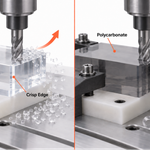
When only a few parts are needed but the test requires the actual stock material, plastic CNC machining may also be worth comparing. It preserves the material grade but does not reproduce the flow, orientation, or shrinkage history created by injection molding.
Define “Functional” with a Validation-Evidence Ladder
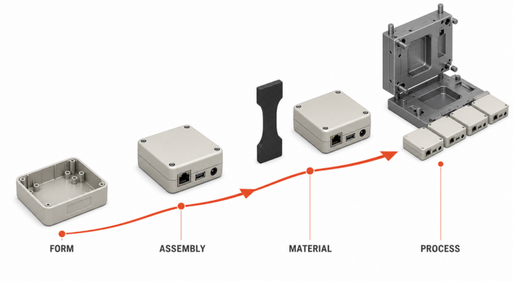
“Functional prototype” is not one acceptance state. The team should identify the evidence level required before selecting the process, because a part that passes an assembly check may still be unsuitable for a durability or production-process decision.
| Evidence level | Question to answer | Vacuum casting fit | Injection molding fit |
| 1. Form and appearance | Are the shape, color, texture, grip, and visible faces correct? | Often suitable, subject to master quality and finishing controls | Capable, but rigid-tool commitment may be premature when material or process evidence is unnecessary |
| 2. Assembly and short-term function | Do snaps, gaps, buttons, sealing interfaces, or brief loads meet the target? | Suitable when the polyurethane datasheet and test conditions match | Tests the actual resin, but trial-tool conditions must still be separated from final production conditions |
| 3. Material-dependent durability | Will the part pass creep, fatigue, impact, chemical, UV, or thermal cycling requirements? | Suitable only when the selected polyurethane and test boundary are supported; a similarity label is not enough | More representative with the actual resin, while specimen geometry, molding history, and environment must still match |
| 4. Production process and capability | Are cavity variation, shrinkage, weld lines, appearance, and critical dimensions stable? | Not suitable | Requires representative tooling, equipment, process window, sampling, and acceptance controls |
Each test should state the response variable, load or environment, duration, sample count, and pass criterion. “Validate the snap fit,” for example, should define insertion force, retention force, cycle count, temperature, and failure mode; one successful assembly does not establish fatigue life.
One part can cross several evidence levels. A vacuum-cast build may approve appearance and assembly while leaving material life unresolved, and an injection-molded sample may use the correct resin while leaving production capability unconfirmed if its gate, cooling, cavity layout, or machine differs from the intended production system.
Quantity Alone Cannot Set the Crossover
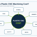
The cost crossover between vacuum casting and injection molding should come from quotations and risk assumptions, not a fixed rule at 100, 500, or 1,000 parts. A practical comparison is:
Total project cost = master/tooling + unit manufacturing × quantity + finishing + inspection + expected change/rework + transition validation
Vacuum casting usually starts with a lower tooling commitment, but silicone condition changes with geometry, resin, surface requirements, and demolding difficulty. Injection molding starts with a larger tool commitment, yet a stable design and continuing demand can distribute that cost across more parts.
Compare the initial batch, follow-on demand, expected design revisions, assumed mold life, material, finish, inspection, and delivery schedule in the same quote model. A unit-price comparison alone misses the cost of tool changes and the validation work required when the project moves from polyurethane to thermoplastic.
Test the Cost Conclusion Across Three Commercial Scenarios
A single quantity forecast is not enough to approve a mold. Compare at least three scenarios—design change, demand uncertainty, and required material evidence—using the same cost boundary for each option.
| Project scenario | Main exposure | More useful comparison |
| The design is likely to change | A rigid tool may need modification or replacement; a new revision can also require another master and silicone mold | Compare the total cost to reach the next valid decision, not the lowest theoretical lifecycle unit price |
| The design is stable but demand is uncertain | Early tooling and inventory can absorb cash; repeated casting can accumulate mold-replacement and labor costs | Model conservative, base, and growth demand, and show when cash is committed in each case |
| Demand is stable and the specified material is required | Casting cannot supply final-resin evidence; a trial injection tool may still differ from production | Include material validation, tool trials, corrections, first-article inspection, and production ramp-up in the molding case |
Record both the probability and consequence of a design change. A small radius, snap, or cosmetic-face revision may require a new master and soft mold for casting, while the same change in an injection mold can affect an insert, parting surface, slide, gate, cooling channel, or even the tool concept.
The model should also show cash timing, not only the final total. Casting can distribute spending across several short batches, while injection molding places more expenditure in mold design, machining, and trials; that distinction matters when the product has not completed technical or market validation.
Both Processes Need DFM, but the Failure Modes Differ
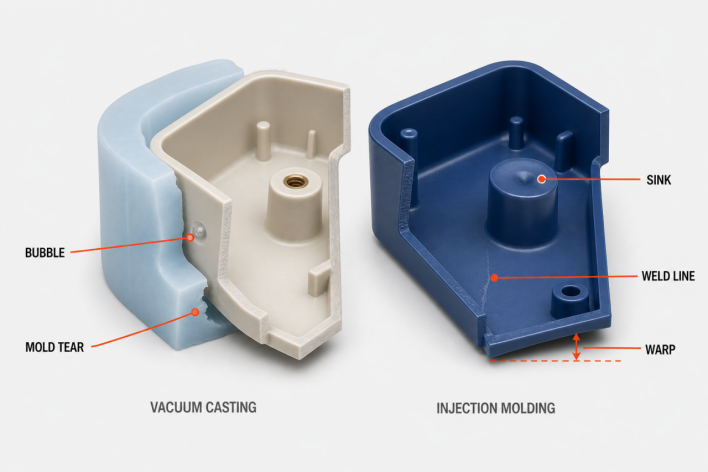
| Review area | Vacuum-casting risk | Injection-molding risk |
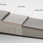
| Master and surface | Layer lines, tool marks, or repairs on the master can be replicated | Tool surface, gate, and ejector locations affect visible faces |
| Wall and mass distribution | Thin regions may not fill reliably; bulky sections can increase cure variation and distortion | Non-uniform walls raise the risk of sink, voids, warpage, and uneven cooling |
| Demolding | Deep undercuts and sharp features can tear silicone or damage the casting | Undercuts may require side actions, lifters, inserts, or a design change |
| Draft | Flexible tooling can tolerate some geometry, but release path still affects mold life | Vertical faces normally need draft matched to texture, depth, resin, and ejection |
| Dimensional control | Master accuracy, silicone, resin cure, and mold wear all contribute | Toolmaking, resin shrinkage, packing, cooling, and the process window all contribute |
| Defect control | Bubbles, incomplete fill, flash, cure distortion, and replicated surface defects | Sink, warp, short shots, weld lines, flash, and ejector marks |
Injection-molding DFM should resolve the parting line, gate, ejection, wall transitions, ribs and bosses, undercuts, and critical dimensions before tool release. Vacuum-casting DFM should define master acceptance, fill and vent strategy, demolding sequence, fragile regions, and the criteria for replacing a worn silicone mold.
Define the Inspection Plan Before Comparing Quotes
Unit price and lead time are not directly comparable when suppliers use different definitions of an acceptable part. The request for quotation should state the critical quality characteristics, measurement methods, sampling plan, and treatment of nonconforming parts.
| Quality-control item | Vacuum-casting plan | Injection-molding plan |
| Reference basis | Approved master, appearance sample, and CAD revision | Approved CAD, tool revision, limit samples, and first article |
| Material | Polyurethane product name, datasheet, lot, mix, and cure conditions | Complete resin grade, color, filler or additive package, lot documentation, and drying requirement |
| Dimensions | Mark critical dimensions and define checks at the first, middle, and later stages of silicone-mold use | Identify first-article and critical dimensions by cavity; confirm shrinkage compensation and fixtures when needed |
| Appearance | Define visible faces, color and texture references, and limits for flash, bubbles, repairs, and mold lines | Define visible faces and limits for gate or ejector marks, weld lines, sink, texture, and color |
| Traceability | Link the master revision, silicone-mold identifier, resin lot, casting batch, and repair record | Link the tool revision, cavity, resin lot, machine, process batch, and inspection record |
| Release gate | Master approval, first-part approval, and mold-replacement criteria | Trial issues closed, first-article approval, and any required process confirmation |
Not every dimension needs the same inspection intensity. Assembly interfaces, sealing faces, locating datums, thin sections, and appearance-critical surfaces should enter the critical-to-quality list, while lower-risk dimensions can use sampling proportionate to their consequence.
Measurement state can also change the result. Thin or compliant cast parts may respond to fixture force and temperature, while molded thermoplastics can continue changing as they cool or condition after ejection, so the drawing or inspection plan should define measurement time, temperature, support, fixture, and conditioning state.
Choose Vacuum Casting When the Design Still Needs Learning
Vacuum casting is generally the stronger candidate when these conditions apply:
- assembly, user, or appearance feedback may still change the geometry;
- the team needs a visually consistent batch rather than one model;
- the current test can use a datasheet-reviewed polyurethane property analogue;
- production tooling is not approved, or a bridge batch is required;
- the inspection plan can manage soft-tool wear, manual operations, and batch variation.
Do not treat vacuum casting as final process evidence when certification, service life, or acceptance depends on the actual thermoplastic grade.
Choose Injection Molding When the Material and Process Are Part of the Test
Injection molding should be evaluated first when these conditions apply:
- geometry and interfaces have reached design release;
- testing requires the specified resin grade, reinforcement, color system, or flame-retardant package;
- performance depends on molding shrinkage, gates, weld lines, fiber orientation, or texture;
- demand is repeatable and the quote model supports the tooling commitment;
- critical dimensions, cosmetic standards, inspection methods, and change control are defined.
A stable CAD model is not by itself a tool-release decision. Unmoldable undercuts, poor wall transitions, inadequate draft, gate restrictions, and ejection risk still need closure before mold design begins.
Five Gates for Moving from Vacuum Casting to Injection Molding
Confirm these points before approving an injection mold:
- The CAD revision and assembly interfaces are frozen, with ownership and cost rules for later changes.
- The target resin grade, color, reinforcement, and regulatory requirements are defined beyond a generic label such as “ABS” or “PC.”
- Initial, annual, or lifecycle demand is included in a total-cost model with tooling maintenance and design-change assumptions.
- Injection-molding DFM has closed wall, draft, gate, parting, ejection, undercut, and critical-dimension risks.
- First-article, dimensional, cosmetic, material-document, and functional acceptance plans are agreed.
Vacuum-casting data can still support the transition, but the team should separate “appearance and assembly validated” from “production material and molding process validated.” That evidence boundary prevents a successful polyurethane build from becoming an unsupported production approval.
Frequently Asked Questions
Can both vacuum casting and injection molding incorporate metal inserts?
Both processes may integrate metal inserts, but the retention method and validation value differ. A casting may encapsulate an insert during pouring or receive it after molding, while injection molding can use insert molding; pull-out, torque, thermal-cycle, or sustained-load acceptance still requires the planned material, interface design, and process.
How should color and gloss be approved across cast and injection-molded parts?
Use controlled lighting and viewing conditions with an approved physical color or limit sample rather than relying only on a screen value. Pigmentation, painting, and finishing in vacuum casting differ from the resin, tool texture, and as-molded surface in injection molding, so cast-part approval does not automatically approve molded appearance.
Should both processes use the same parting-line location?
A silicone mold split is selected to release the master and casting and to make flash removal manageable, so it does not transfer directly to a rigid injection mold. Injection-mold parting also depends on opening direction, shutoffs, side actions, venting, ejection, and cosmetic faces; a split that works in soft tooling may create weak steel conditions or visible flash in a production tool.
How can a project prevent revision mix-ups when cast and molded parts coexist?
Identify the CAD revision, manufacturing process, material, master or tool revision, and acceptance status on batch labels, packaging, and inspection records. Assembly and test records should also reference the specific part batch so that polyurethane results are not assigned to thermoplastic molded parts and old revisions do not enter a new build.
Can the original master be reused after a local geometry change?
Reuse is reasonable only when repair or remachining can control the revised geometry, datums, and surface condition. The modified master still needs a new approval and revision identifier, and an existing silicone mold does not inherit the master change, so a replacement mold is normally required.
Can a clear vacuum-cast part validate the optical performance of a clear production molding?
A clear polyurethane casting can support shape, assembly, viewing-area, and approximate light-path evaluation, but visual clarity does not establish the transmission, haze, stress response, aging, or chemical resistance of the target thermoplastic. When those characteristics control acceptance, test the specified material, thickness, surface condition, and molding process.
A Six-Step Engineering Decision Workflow
- Define the validation question. State the engineering or commercial decision this batch must support and the rework, delay, or acceptance risk created by a wrong conclusion.
- Classify the evidence level. Separate appearance, assembly, short-term function, material durability, and production-process capability so that lower-level evidence does not become a higher-level approval.
- Screen out unsuitable routes. Use the specified material, geometry, undercuts, wall strategy, visible faces, and delivery need to remove any process that cannot supply the evidence or manufacture the part reliably.
- Quote the same scenarios. Give suppliers the same CAD, quantities, change assumptions, material, finish, and inspection scope, and ask them to separate tooling, unit manufacturing, finishing, and validation costs.
- Agree on acceptance. Before production, confirm critical-to-quality features, measurement state, sample count, cosmetic limits, material documents, traceability, and disposition of nonconforming parts.
- Record the transition gate. Document what the build proves, what it does not prove, and which design, material, or process issues must close before injection molding or production release.
The output is an auditable decision record, not merely a process name. If the project starts with vacuum casting, define the conditions that trigger a new injection-molding comparison; if it starts with injection molding, record how representative the tool is and how far the trial data can support a production conclusion.
Make the Final Choice with Project Inputs
Provide the supplier with the CAD model, target material or properties, initial and follow-on quantities, critical dimensions, cosmetic faces, color or texture, service environment, test plan, and required date. A fixed volume rule is only a guess when these inputs are missing.
PlasticHubs can compare vacuum casting, low-volume production, and an injection-molding path from the same project inputs. Submit the CAD file and validation requirements to confirm whether the next build must prove appearance and assembly, material behavior, or the production molding process before committing to a rigid tool.