A process that looks right in CAD can still fail at the interface: an insert may shift under injection pressure, or an overmold may peel from its substrate after use. The choice depends on what the molded part must integrate and how that interface will carry load, seal, insulate, or feel in the user’s hand. Choose insert molding to capture a premade component inside plastic; choose overmolding to add a second molded material to an existing substrate. Some parts need both processes in sequence.
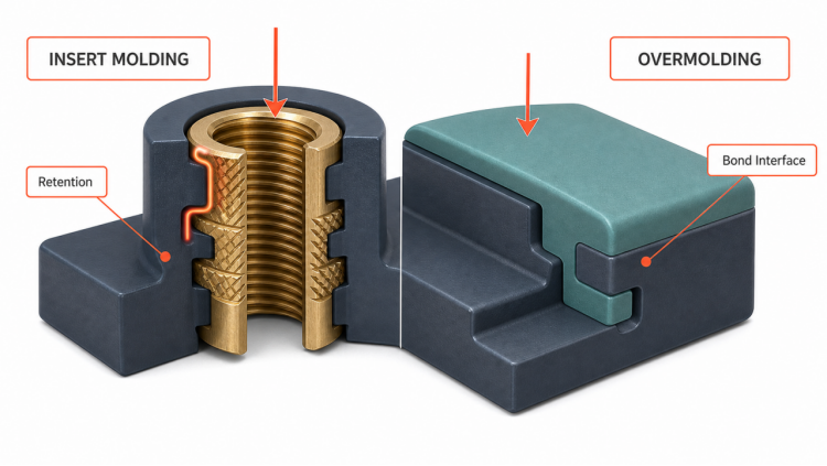
Overmolding vs Insert Molding: The Decision in One Table
| Decision point | Insert molding | Overmolding |
| What is integrated? | A premade item, often metal or another rigid component | A second molded material over a substrate |
| Main purpose | Add threads, contacts, reinforcement, wear surfaces, magnets, or other embedded functions | Add grip, sealing, cushioning, insulation, protection, color, or texture |
| Typical examples | Threaded brass insert in a housing, electrical pin in a connector, bushing in a plastic lever | Soft grip on a rigid handle, elastomer seal on a housing, protective layer around a substrate |
| How the interface holds | Encapsulation plus geometric retention such as knurls, grooves, holes, flanges, or undercuts | Chemical adhesion, mechanical interlocking, or both |
| Main tooling concern | Locate and restrain the insert without damage or plastic leakage | Locate the substrate and control second-material flow across the intended boundary |
| Common failure risk | Insert movement, rotation, pullout, surrounding plastic cracks, flash, or incomplete encapsulation | Peeling, delamination, poor fill, trapped air, flash, or an irregular bond line |
The table gives the fastest choice, but the final answer depends on interface geometry, material behavior, loads, environment, and inspection. Process names can overlap in casual use, so define the architecture in the RFQ instead of relying on the label alone.
Choose by What Must Become Part of the Plastic Component
Insert molding starts with an item that already exists before the molding cycle. That item is loaded into the tool, held in position, and surrounded partly or fully by injected plastic. Threaded inserts, electrical contacts, pins, bushings, sleeves, mesh, and magnets are common examples.
Overmolding starts with a substrate that receives another molded layer or feature. The substrate may be a previously molded rigid plastic component, a metal component, or another compatible material. The added material supplies a function at the surface or interface, such as a compliant seal, impact protection, electrical insulation, or a soft-touch grip.
This distinction is functional rather than purely linguistic. A supplier may describe plastic molded around a metal component as either insert molding or metal overmolding. Specify the insert or substrate, molding sequence, coverage area, retention method, and acceptance test so the manufacturing requirement remains clear.
The Interface Decides Whether Either Process Works
Both processes remove a later assembly step by forming an integrated component in the mold. They fail for different physical reasons, so the interface needs a process-specific design.
Overmolding depends on adhesion, interlock, and surface condition
A second material does not bond reliably to every substrate. Polymer family, grade, additives, moisture, surface energy, mold temperature, material temperature, and time between molding stages can all affect adhesion. A pairing that bonds in a material chart still needs representative testing with the specified grades and process conditions.
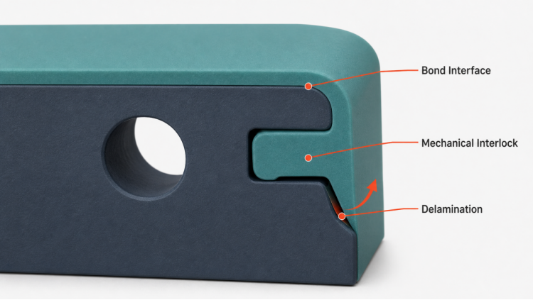
Mechanical features can support or replace chemical adhesion. Through-holes, slots, edge wraps, recesses, ribs, and undercuts give the overmold a physical path to lock around the substrate. These features are especially valuable when the materials have limited chemical affinity or when the part will see repeated peel loading.
The bond line also needs protection from contamination and trapped gas. Mold release, oil, dust, moisture, or handling residue can reduce adhesion, while poor venting can leave short shots, burn marks, or voids near the interface. A thin feather edge may look clean in CAD but can be hard to fill and easy to lift during use.
Insert molding depends on location, retention, and support
The tool has to hold an insert against melt flow and injection pressure without scratching, bending, or crushing it. A locating feature that controls only one end may allow the insert to tilt or rotate. The mold design therefore needs positive location, stable support, and a sealing strategy where plastic must not enter threads, contact areas, or other protected surfaces.
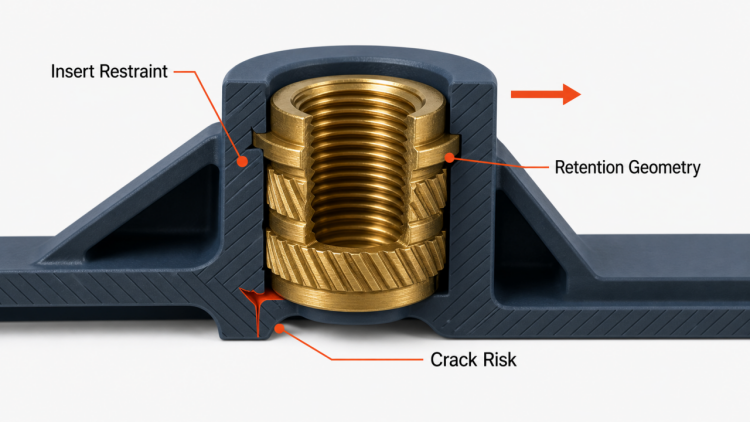
Retention geometry transfers the service load from the insert into the molded body. Knurls, grooves, cross-holes, flats, flanges, and undercuts can resist pullout or torque, but sharp transitions may concentrate stress in the plastic. Adequate plastic support around the insert matters as much as the insert feature itself.
Temperature differences add another risk. A cold metal insert can cool the melt locally and affect fill or weld-line behavior, while thermal expansion mismatch can create residual stress as the part cools. Preheating, gating, material selection, and geometry may need adjustment, but the right control depends on the insert and resin rather than one universal rule.
Compare Materials, Geometry, Tooling, and Quality Control
| Engineering dimension | Insert molding question | Overmolding question |
| Material | Can the insert tolerate molding temperature and pressure, and is it clean and dimensionally controlled? | Are the exact substrate and overmold grades compatible under the intended process conditions? |
| Geometry | Is there enough supported plastic around retention features without creating a crack-prone section? | Can the second material flow, vent, and lock into the interface without weak feather edges? |
| Tooling | How will the tool locate, restrain, and seal around the insert? | How will the tool locate the substrate and define the overmold boundary? |
| Loading | Will the interface see pullout, torque, bending, compression, or thermal stress? | Will the interface see peel, shear, compression set, wear, fluid exposure, or thermal cycling? |
| Appearance | Which insert surfaces must remain exposed and free of flash? | Where may the bond line, gate mark, or material transition be visible? |
| Inspection | Can position, rotation, coverage, and protected features be checked? | Can bond continuity, coverage, dimensions, and cosmetic limits be checked? |
| Production flow | Is manual or automated insert loading suitable for the insert shape and control plan? | Will the project use transfer molding, two-shot molding, or another sequence suited to the substrate and quantity? |
Neither process is automatically cheaper. Insert molding may use one molding cycle but adds insert handling, fixturing, and incoming insert control. Overmolding may require a substrate tool plus an overmold tool or a multi-shot setup, along with tighter control of material pairing and the time between stages.
Production quantity affects tooling and automation choices, but it does not create a fixed break-even point that applies to every part. Compare the full route: tooling, loading, cycle time, scrap risk, secondary assembly removed, inspection, and expected design life.
DFM Checks Before You Release Tooling
Bring the interface into the DFM review while geometry can still change. A useful RFQ package includes:
- 3D CAD and a controlled drawing: Identify critical dimensions, datums, protected surfaces, and cosmetic boundaries.
- Exact material grades: Name the substrate resin, overmold material, colorant, filler, and any additives that could affect flow or adhesion.
- Insert specification: Provide material, finish, dimensional tolerances, supplier drawing, orientation, and surfaces that must remain free of plastic.
- Interface geometry: Show knurls, grooves, holes, edge wraps, undercuts, shutoffs, and the intended material boundary.
- Service loads: State expected pull, torque, peel, compression, impact, wear, or cable forces and where they enter the part.
- Use environment: Include fluids, cleaning agents, UV exposure, operating temperature range, humidity, and sterilization or cycling needs when applicable.
- Sealing requirement: Define the leak path, pressure or ingress condition, mating components, and acceptance method rather than writing only “waterproof.”
- Appearance criteria: Mark visible surfaces and acceptable limits for flash, gate marks, witness lines, color variation, and substrate read-through.
- Inspection plan: Identify dimensions and interface features that can be measured, visually checked, leak-tested, pull-tested, or torque-tested.
- Validation samples: Reserve time for representative molded samples and functional testing before the production setup is frozen.
This package helps the molder evaluate tool access, insert restraint, material flow, venting, shutoffs, interface thickness, and testability. It also exposes requirements that conflict—for example, a hidden bond line may force a gate or shutoff change that affects flow.
Can One Part Use Both Insert Molding and Overmolding?
Yes. A rigid plastic housing may first be molded around threaded metal inserts, creating durable fastening points. The insert-molded housing can then become the substrate for an elastomer overmold that adds a perimeter seal, impact pad, or grip.
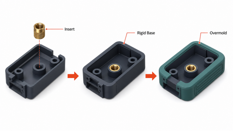
The sequence increases the number of interfaces that require control. The first molding step must keep the insert in position, and the second must not distort the substrate or contaminate protected insert features. Datums and inspection points need to survive both operations so later measurements still refer to the functional geometry.
A hybrid route makes sense when the finished part needs two distinct functions that cannot be provided by one material system. It is a poor fit when the same result can be achieved with simpler geometry, a separately assembled seal, or a post-installed insert at lower total risk.
Prototype and Validate the Interface Before Production
Prototype work needs to represent the interface question, not just the outer shape. A soft material cast over a printed substrate may help assess grip or access, but it may not predict adhesion in the production resin and molding cycle. State which risks the prototype can and cannot test.
For insert-molded parts, validation may include insert position, rotation, pullout, torque, thread function, electrical continuity, sectioning, or dimensional change after environmental cycling. For overmolded parts, relevant checks may include peel or shear behavior, seal leakage, compression response, wear, chemical exposure, thermal cycling, and visual inspection of the bond line.
Acceptance values come from the product requirement, not from the process name. Link each test to a use load, safety factor, environmental condition, mating part, or cosmetic standard, then run it on samples made with the intended materials and representative tooling conditions.
Frequently Asked Questions
Is insert molding the same as overmolding?
They are related molding methods, and terminology sometimes overlaps. For process selection, insert molding usually means molding plastic around a premade component, while overmolding usually means molding a second material onto a substrate. Define the part architecture and sequence in the RFQ.
Can overmolding bond without an adhesive?
Yes, when the material pair and molding conditions support direct adhesion, or when geometry creates a mechanical lock. Direct bonding is grade-specific, so confirm the pairing with material data and representative molded samples.
What materials can be used for insert molding?
Metal inserts such as brass or steel are common, but premade plastic components, contacts, bushings, magnets, and other items may also be insert molded. The insert must tolerate the molding environment and provide controllable location, sealing, and retention features.
Why does an overmold peel from the substrate?
Common causes include incompatible grades, contamination, insufficient temperature at the interface, weak mechanical interlocking, trapped gas, poor fill, or a geometry that concentrates peel stress. Failure analysis needs to separate material adhesion from tool, process, and part-design causes.
Can a threaded insert be added after molding instead?
Often, yes. Heat-set, ultrasonic, press-fit, or other post-installed insert methods may simplify molding, but they add a secondary operation and have different retention, stress, and access constraints. Compare both routes using the required torque, pullout, plastic thickness, service temperature, and production flow.
Bring the Interface Risk into the RFQ
The best overmolding vs insert molding decision is the one tied to a defined interface, load case, environment, and acceptance test. Send PlasticHubs your CAD model, drawing, material grades, insert data, expected loads, cosmetic boundaries, sealing needs, and validation plan. Contact PlasticHubs for a process-fit and DFM review before the tooling route is fixed.