
Plastic printing machines28 SLS · 19 MJF · 22 SLA · 34 FDM
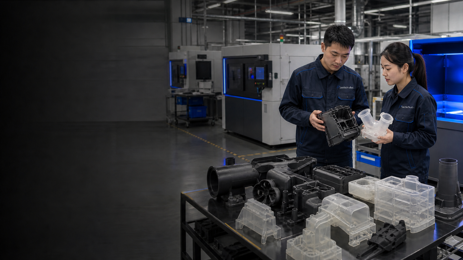
PLASTICHUBS PLASTIC 3D PRINTING SERVICES
Plastic 3D Printing Services for Prototypes and Low-Volume Parts
Order SLA, MJF, SLS, or FDM prototypes and production parts from a plastic-focused manufacturing team. Material selection, finishing, threaded inserts, assembly, engineering review, and inspection can be included in one project.
- 103 plastic 3D printers listed across SLS, MJF, SLA, and FDM workshops
- Two self-operated printing centers covering more than 4,000 m², plus a 20+ factory cooperation network
- ISO 9001, ISO 13485, and AS9100 certified quality systems
Final process, material, dimensional plan, and finish are confirmed after file review.
Self-operated centersMore than 4,000 m² of shared production space
Cooperation factoriesAdditional qualified capacity for project routing
Certified quality systemsISO 9001 · ISO 13485 · AS9100
WHY PLASTICHUBS FOR PLASTIC 3D PRINTING
Plastic 3D printing, finishing, inspection, and delivery in one project
PlasticHubs provides SLA, MJF, SLS, and FDM production for visual prototypes, functional nylon parts, jigs, fixtures, housings, ducts, presentation models, and low-volume end-use parts.
The deliverable can include more than a raw print. Material selection, cleaning, dyeing, sanding, painting, threaded inserts, bonding, assembly, drawing-based dimensional checks, and visual inspection can be included in the same project.
Use the process cards and capability table below to shortlist a route. Final process, material, orientation, finishing, and inspection requirements are confirmed against the part file and accepted quotation.
View our 3D printing services →OUR 3D PRINTING SERVICES
Compare PlasticHubs SLA, MJF, SLS, and FDM services
Compare each process by application, material family, typical accuracy, feature guidance, finishing compatibility, and available build size.
01Powder bed
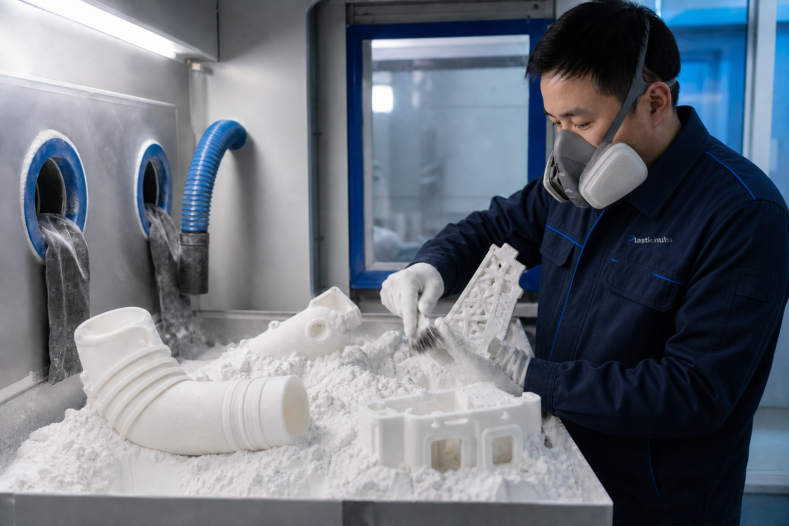
SLS 3D Printing
Good for functional nylon prototypes, complex assemblies, ducts, brackets, and parts that benefit from a support-free build.
- PA12, glass-filled PA12, and FS 3400GF
- Typical reference: ±0.3 mm; >100 mm: 0.35%
- Maximum referenced envelope: 680 × 360 × 560 mm
02Powder bed
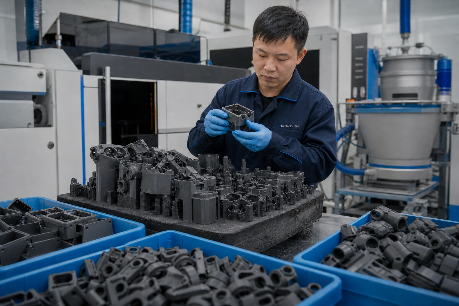
MJF 3D Printing
Suitable for functional nylon parts and low-volume batches of compact components where build density and consistent mechanical behavior matter.
- PA12 functional parts
- Typical reference: ±0.2 mm; >100 mm: 0.25%
- Maximum referenced envelope: 380 × 280 × 380 mm
03Photopolymer
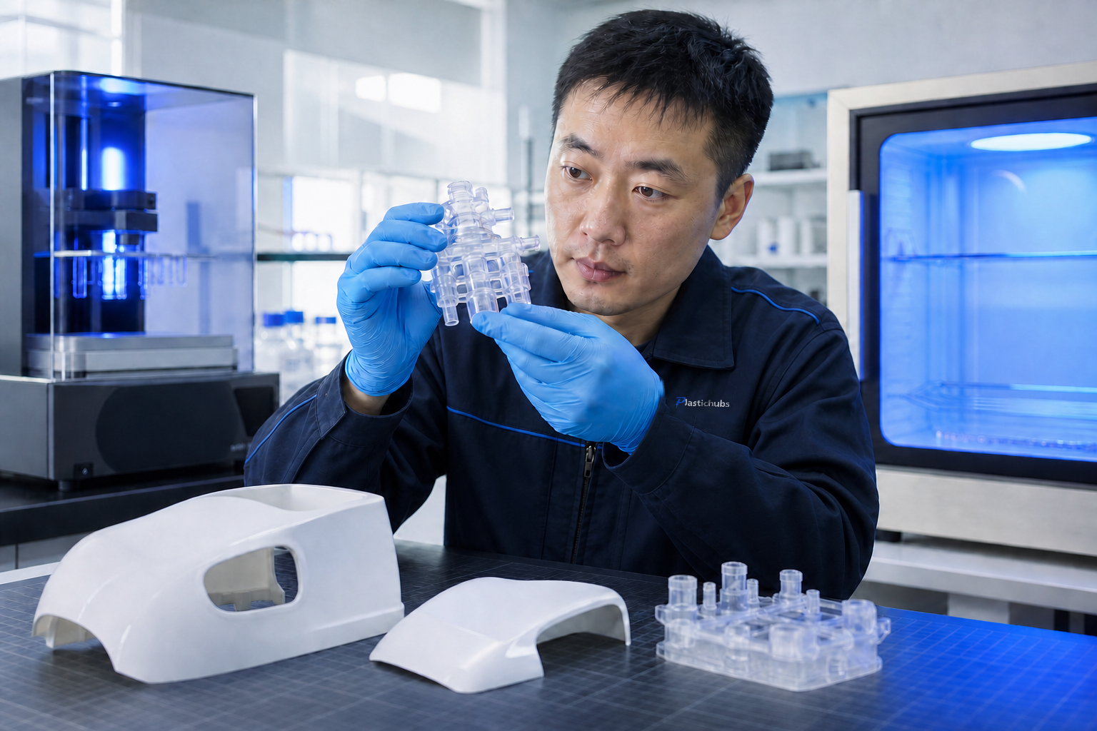
SLA 3D Printing
Best suited to visual prototypes, fine features, master patterns, and housings when detail and a smooth cosmetic surface are the main priorities.
- Tough, translucent, high-temperature, and ABS-like resins
- Typical reference: ±0.2 mm; >100 mm: 0.15–0.25%
- Maximum referenced envelope: 1400 × 700 × 500 mm
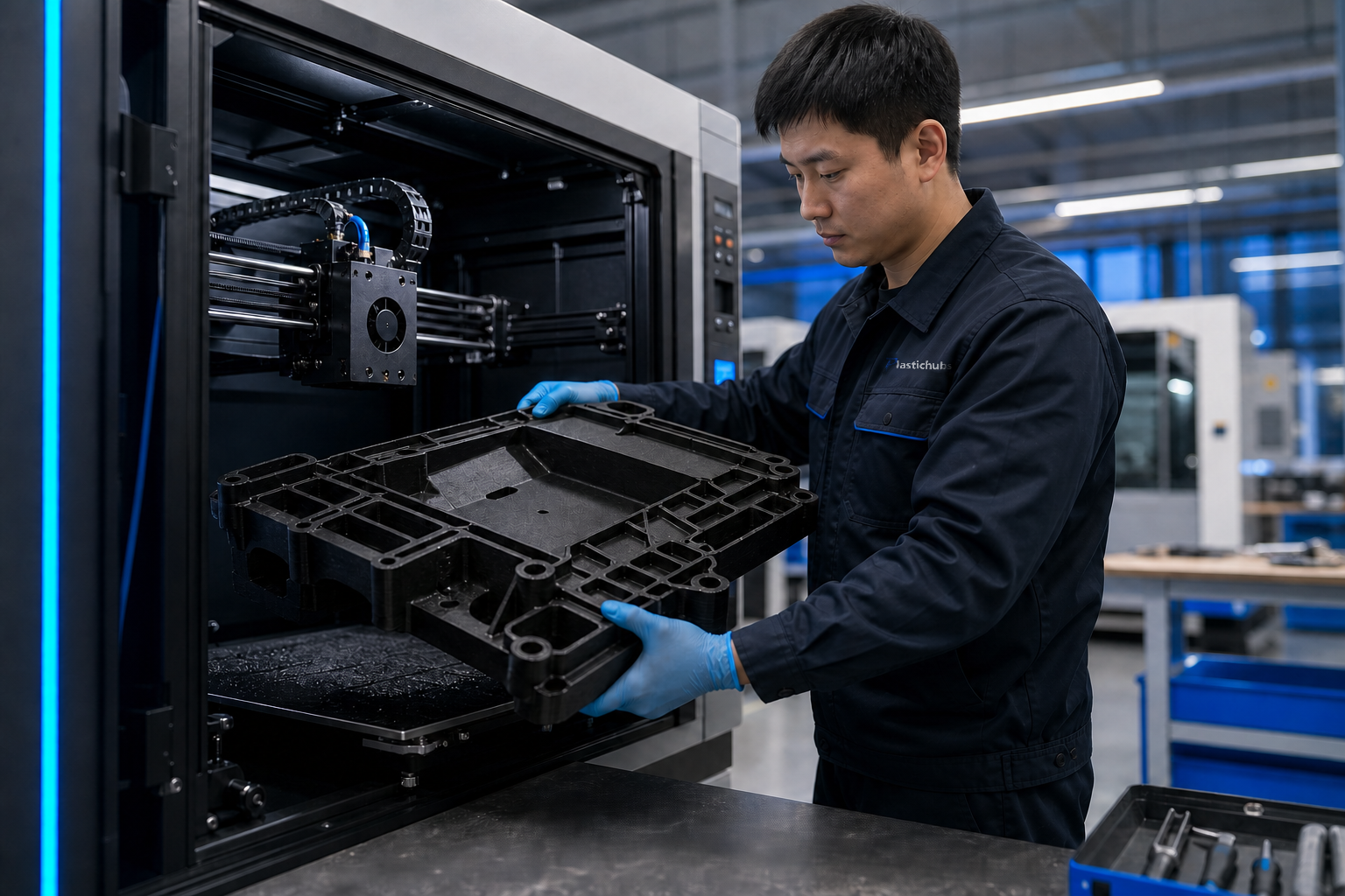
04Material extrusion
FDM 3D Printing
A practical choice for large-format models, fixtures, early fit checks, and cost-sensitive parts where visible layer lines are acceptable.
- PLA, ABS, ASA, PC, nylon, TPU, ULTEM, PEEK, and reinforced grades
- Large models, fixtures, and shop-floor aids
- Accuracy and build envelope confirmed by material and equipment
Interactive service finder
Not sure which service fits?
Select the main part requirement to compare the most relevant PlasticHubs printing processes.
Relevant PlasticHubs service
SLS or MJF
Powder-bed nylon services suit complex geometry, assembly fit, and functional handling.
| Process | Typical accuracy | Minimum wall / hole size | Referenced maximum build envelope | Lead-time planning |
|---|---|---|---|---|
| SLA | Typical: ±0.2 mm | 0.6 mm / 1.0 mm | 1400 × 700 × 500 mm | Confirmed after file review |
| MJF | Typical: ±0.2 mm | 0.8 mm / 1.2 mm | 380 × 280 × 380 mm | Confirmed after file review |
| SLS | Typical: ±0.3 mm | 0.8 mm / 1.2 mm | 680 × 360 × 560 mm | Confirmed after file review |
| FDM | Confirmed after file review | Confirmed by material and orientation | Confirmed by equipment | Confirmed after file review |
These values are typical references, not universal guarantees. Printing time excludes engineering review, finishing, inspection, packing, and shipping.
MATERIALS AVAILABLE FOR PLASTIC 3D PRINTING
Plastic 3D printing materials by process
Choose materials by function, exposure, load direction, appearance, and assembly requirements—not by material name alone. Grade availability, color, build size, and post-processing are confirmed during quotation.
ISO 9001ISO 13485AS9100
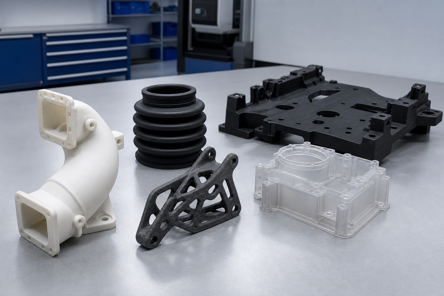
SLA
Photopolymer resins
- ABS-like photosensitive resin
- Green tough resin (8228)
- Imported high-temperature resin (Therm 1)
- Imported material 8000
- Imported black tough resin
- Translucent resin (8001)
- Imported tough resin 6060
MJF
MJF PA12 for production nylon parts
- PA12
- Black or natural finish by project
- Dyeing and selected finishing options
- Functional batches and compact assemblies
SLS
Nylon families
- PA12 white nylon
- Glass-filled PA12
- FS 3400GF
- Support-free complex geometry
- Cleaning, blasting, dyeing, and inserts
FDM
Engineering filaments
- PLA, ABS, ASA
- PETG and PETG ESD
- PC, PC-ABS, PC-PBT, PC-FR
- PA, PA6-CF, PA12-CF
- TPU 95A
- ULTEM 9085 and ULTEM 1010
- PEEK, PEEK-CF, PEEK-GF, PEKK
- PPS and PPSU
Material recommendations start with service conditions.Share load direction, temperature, chemical or UV exposure, assembly method, quantity, finish, and critical dimensions.
Request a material recommendation →3D PRINTING QUOTE
Send the part file and requirements for a project quote
Upload STEP, STP, or STL files. Add a DWG, DXF, or PDF drawing when critical dimensions, tolerances, cosmetic surfaces, inspection points, or acceptance notes must be controlled.
- Process and material recommendation
- Quantity and delivery review
- Finishing, inserts, assembly, and inspection pricing
- No hard tooling required for printed parts
STEPHousing_Assembly.step3D model · ready for review
PDFCritical_Dimensions.pdfDrawing · inspection notes
RFQ inputsFileQuantityMaterialFinishCritical features
HOW TO ORDER 3D PRINTED PARTS
From CAD upload to inspected delivery
The order path is simple, while process selection and inspection remain specific to the part.
Upload CAD
Send the 3D model, drawing, quantity, intended use, and target delivery date.
Engineering review
We review process, material, wall sections, holes, trapped material, interfaces, and finish requirements.
Confirm the quote
Approve process, material, quantity, finish, inspection plan, price, and delivery schedule.
Print and finish
Parts are produced, cleaned, post-processed, fitted with inserts, or assembled as quoted.
Inspect and ship
Visual and dimensional checks follow the accepted file, drawing, and inspection requirements.
POST-PROCESSING
3D printing post-processing services
Choose from cleaning, blasting, dyeing, smoothing, painting, threaded inserts, bonding, and assembly. Available options depend on the printing process, material, geometry, and finish requirements.
Cleaning & Blasting
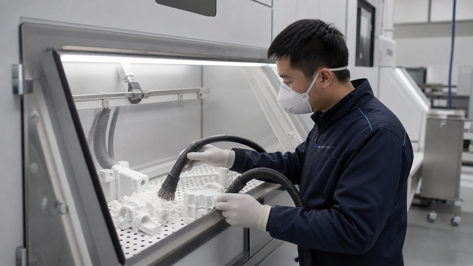
Powder removal, support cleanup, and process-appropriate blasting for cleaner, more uniform printed surfaces.
Request Cleaning & Blasting →Dyeing & Coloring
Color treatment for compatible nylon processes when parts need a more uniform appearance or clear product identification.
Request Dyeing & Coloring →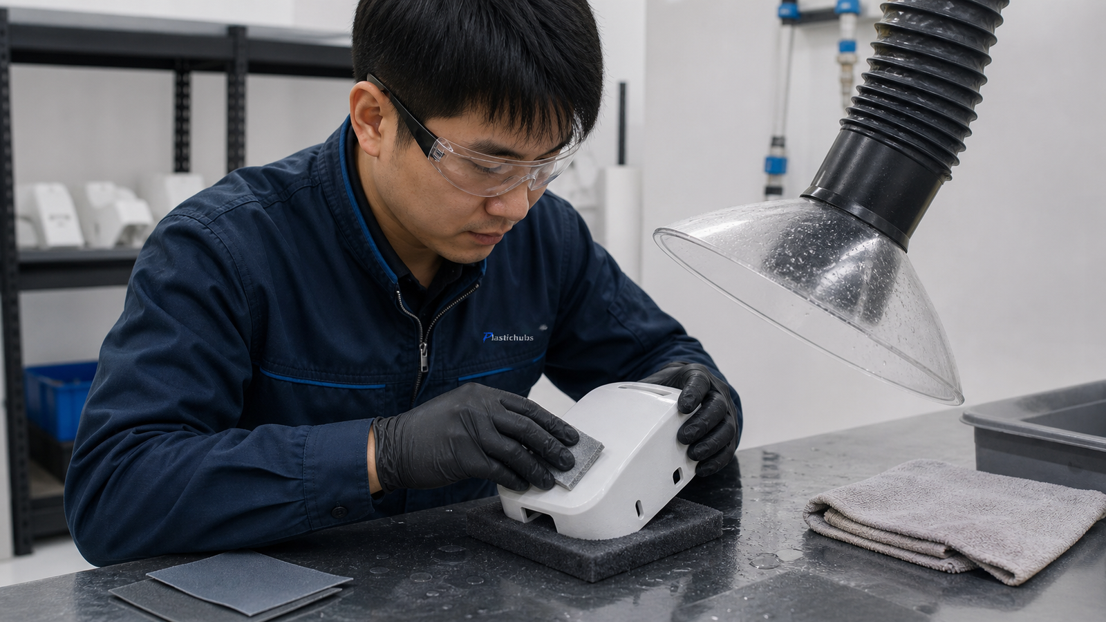
Sanding & Smoothing
Local sanding, surface refinement, and compatible smoothing options for visible faces and presentation parts.
Request Sanding & Smoothing →Painting & Coating
Primer, paint, and selected coatings for compatible materials, with color and cosmetic expectations agreed before production.
Request Painting & Coating →Threaded Inserts
Threaded inserts can be installed when the part provides suitable wall thickness, installation access, and support for the expected load.
Request Threaded Inserts →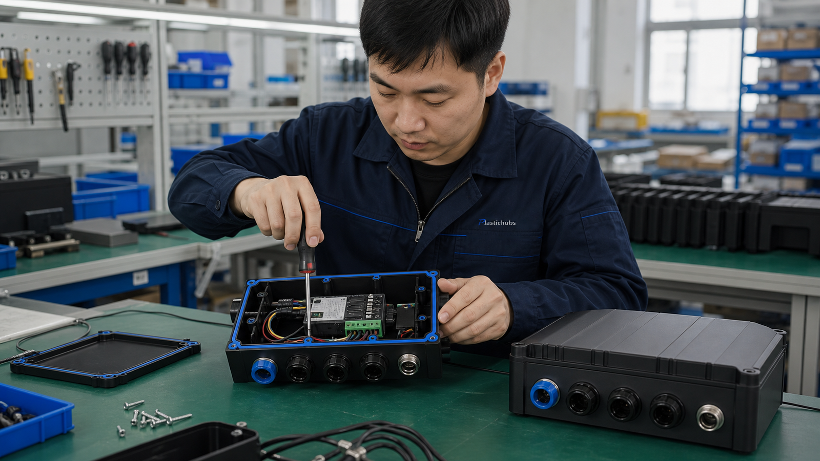
Bonding & Assembly
Bonding and multi-part assembly for designs that require joined components, enclosed geometry, or delivered subassemblies.
Request Bonding & Assembly →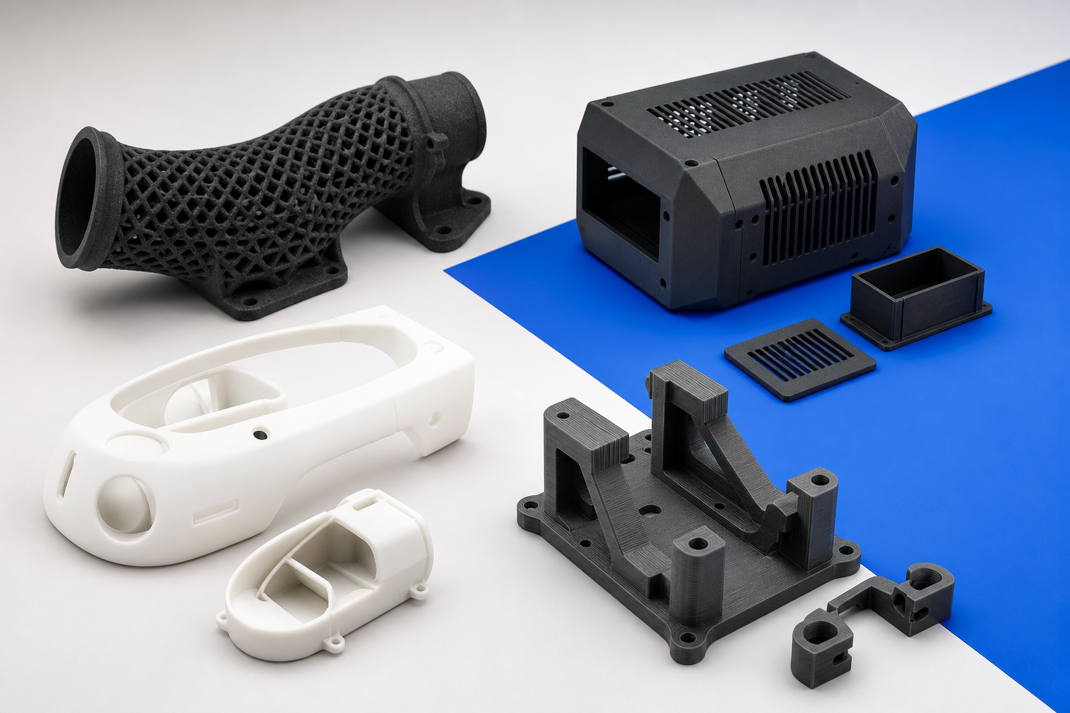 Conceptual process showcase · actual output varies by material and geometry
ENGINEERING APPLICATIONS
Parts for engineering review and production decisions
Use plastic 3D printing to evaluate fit, airflow, component protection, assembly, ergonomics, or appearance. Define the requirement before quotation so the prototype can be assessed against a clear objective.
Housings & enclosuresFit, access, cable routing, visual review
Ducts & manifoldsComplex paths and integrated geometry
Jigs & fixturesAssembly aids, gauges, handling tools
Brackets & connectorsFunctional validation before production
Presentation modelsShape, ergonomics, and finish evaluation
Low-volume partsBridge quantities without hard tooling
ENGINEERING & INSPECTION CAPABILITIES
Engineering review and inspection for printed parts
PlasticHubs can review features that may affect printability, handling, assembly, or inspection. Dimensional and appearance requirements are defined against the submitted part file, drawing, and accepted quotation.
Critical dimensions and fit interfaces
Load direction and repeated-use areas
Thread, insert, snap-fit, or hinge requirements
Cosmetic A-surfaces and color expectations
Temperature, chemical, UV, or moisture exposure
Sealing, airflow, or trapped-material concerns
Available project support
Review and inspection services
- File review: STEP, STP, or STL files, with DWG, DXF, or PDF drawings when dimensions or acceptance requirements need to be controlled.
- Feature review: walls, holes, trapped material, interfaces, supports, and orientation-sensitive areas.
- Dimensional checks: calipers, micrometers, height gauges, go/no-go gauges, or 2.5D/3D measurement as appropriate.
- Visual inspection: surface condition, residue, support marks, color, and visible defects against the agreed reference.
Inspection standards
Visual condition, residue, support marks, color, assembly, and visible defects are checked against the agreed process and finish.
Review quality FAQs →Dimensional inspection
Critical dimensions can be checked with calipers, micrometers, height gauges, pin gauges, thread gauges, or 2.5D/3D measurement as appropriate.
Define inspection points →Feature review within the same project
Walls, holes, channels, trapped material, load direction, fits, inserts, threads, cosmetic faces, and build orientation are reviewed together—not as a separate service page.
Send files for review →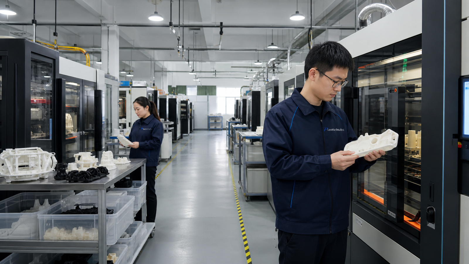
PLASTIC 3D PRINTING SCALE
PlasticHubs capacity across self-operated centers and qualified factories
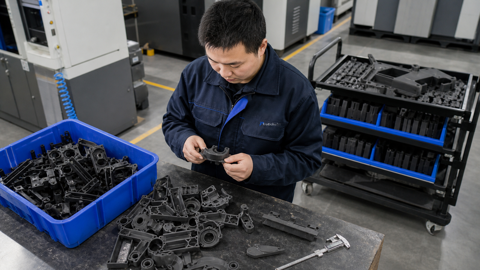
PlasticHubs operates two 3D printing centers covering more than 4,000 m² and coordinates a network of 20+ qualified factories for additional capacity and process coverage.
Machine counts cover the listed plastic SLS, MJF, SLA, and FDM workshops. Final capacity allocation depends on process, material, part size, and schedule.
3D PRINTED PART SHOWCASE
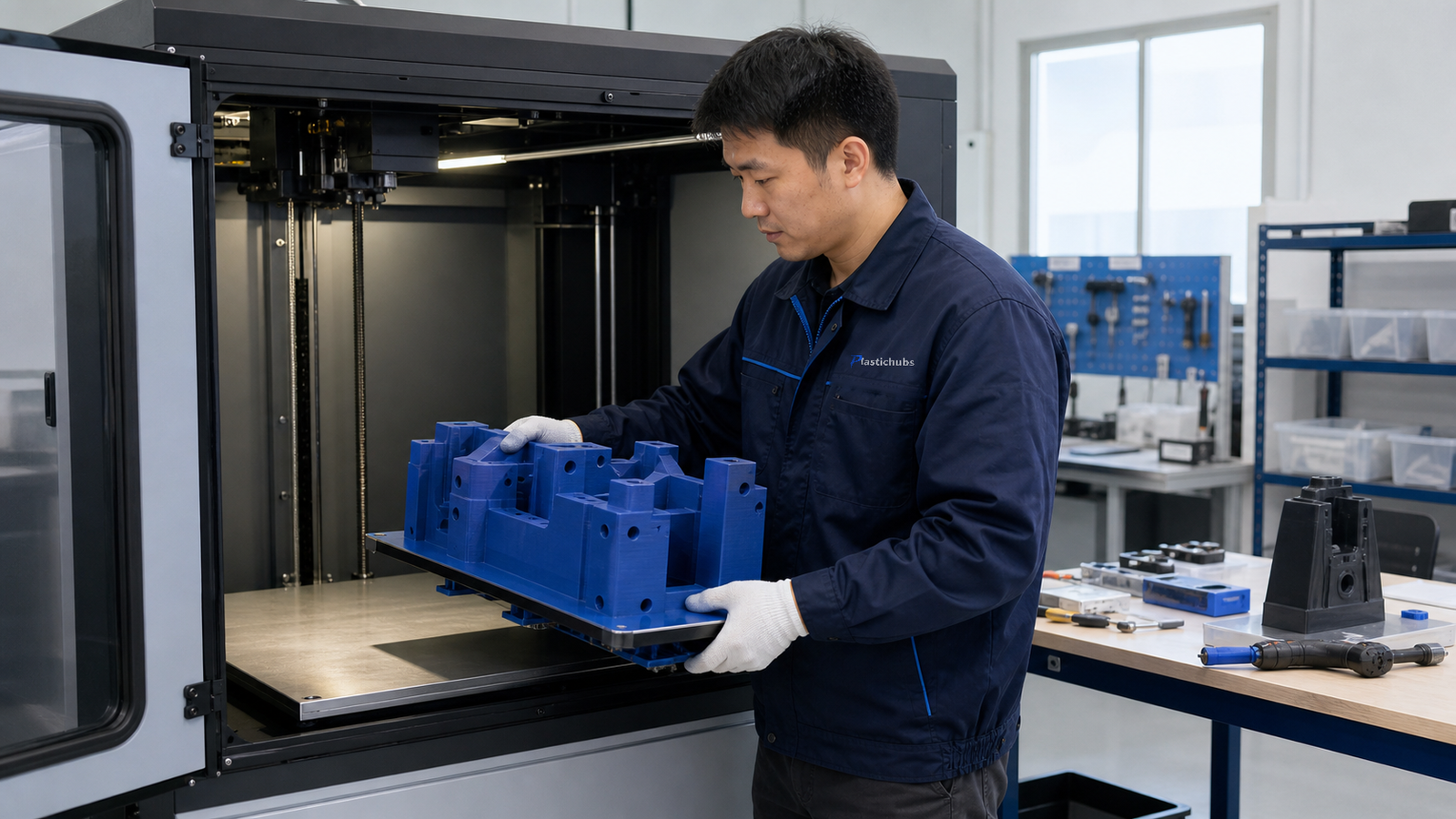
From prototypes to assembled plastic parts
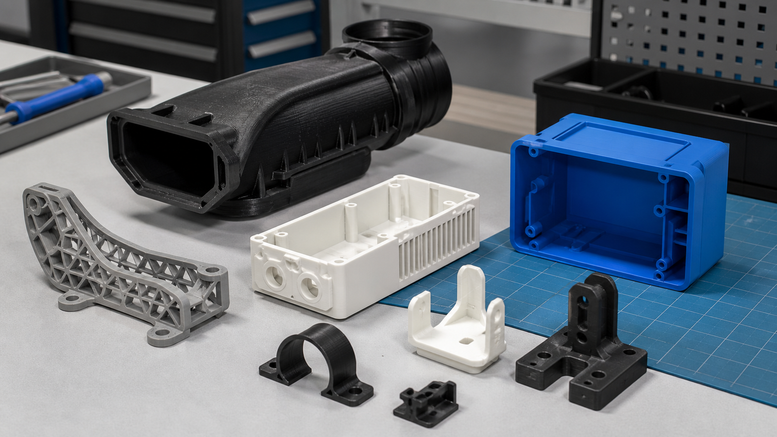
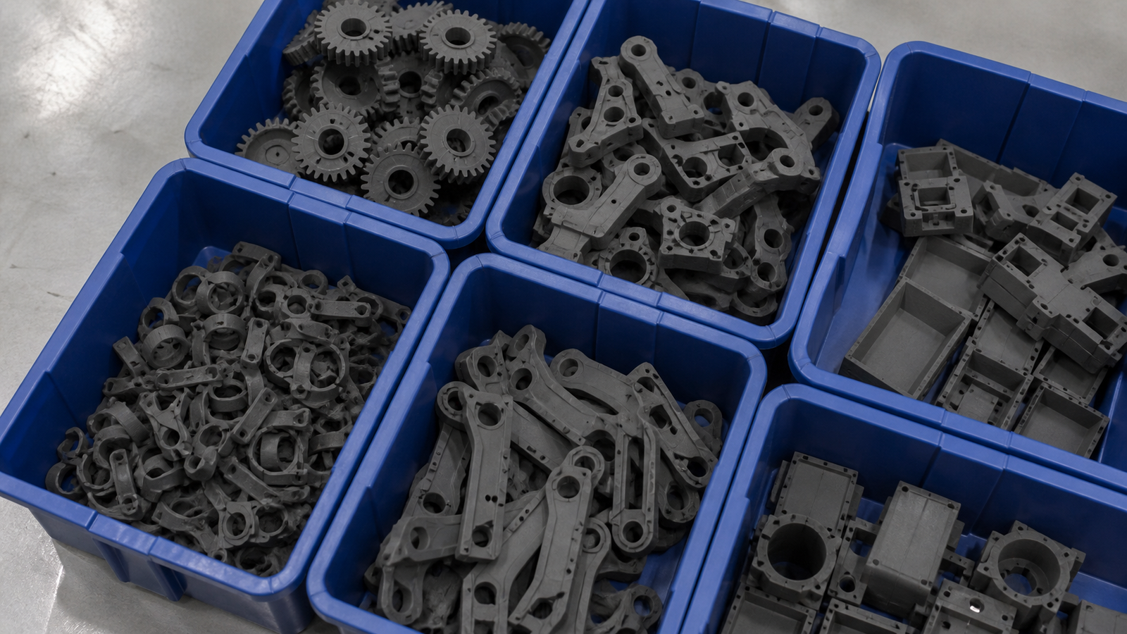
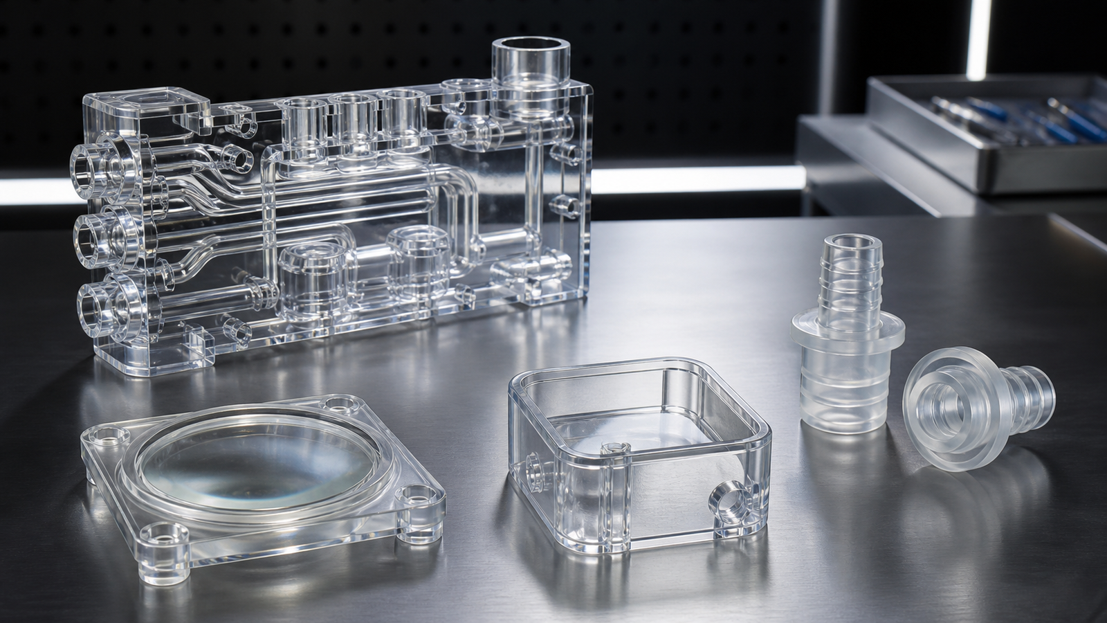
Representative parts show the range of geometry, surface, scale, and end-use context available across the four plastic printing processes.
INDUSTRIES WE SUPPORT
Plastic 3D printing for product development and production teams
We support prototype, tooling, assembly, airflow, enclosure, and low-volume part requirements across multiple engineering sectors.
Robotics & automationRobot housings, end-of-arm tooling, grippers, brackets, guards, and functional prototypesUAV & aerospaceDucts, lightweight brackets, fixtures, and fit-check partsMedical devicesDevelopment models, equipment housings, fixtures, and controlled inspection requirementsElectronicsEnclosures, cable guides, thermal and airflow prototypesAutomotiveInterior prototypes, ducts, jigs, fixtures, and low-volume componentsConsumer productsErgonomic models, appearance prototypes, and assembled housings
REPRESENTATIVE PROJECT EXAMPLES
How plastic 3D printing supports real engineering work
These anonymized examples reflect PlasticHubs manufacturing experience; customer identities and confidential design details are not shown.
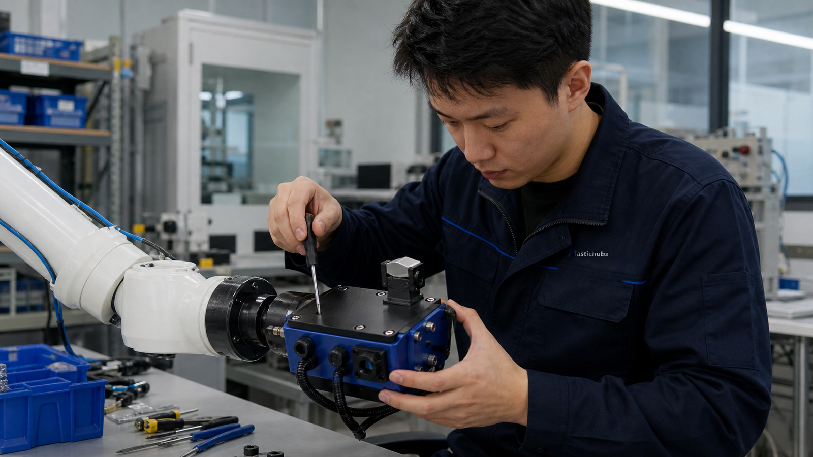
ROBOTICS
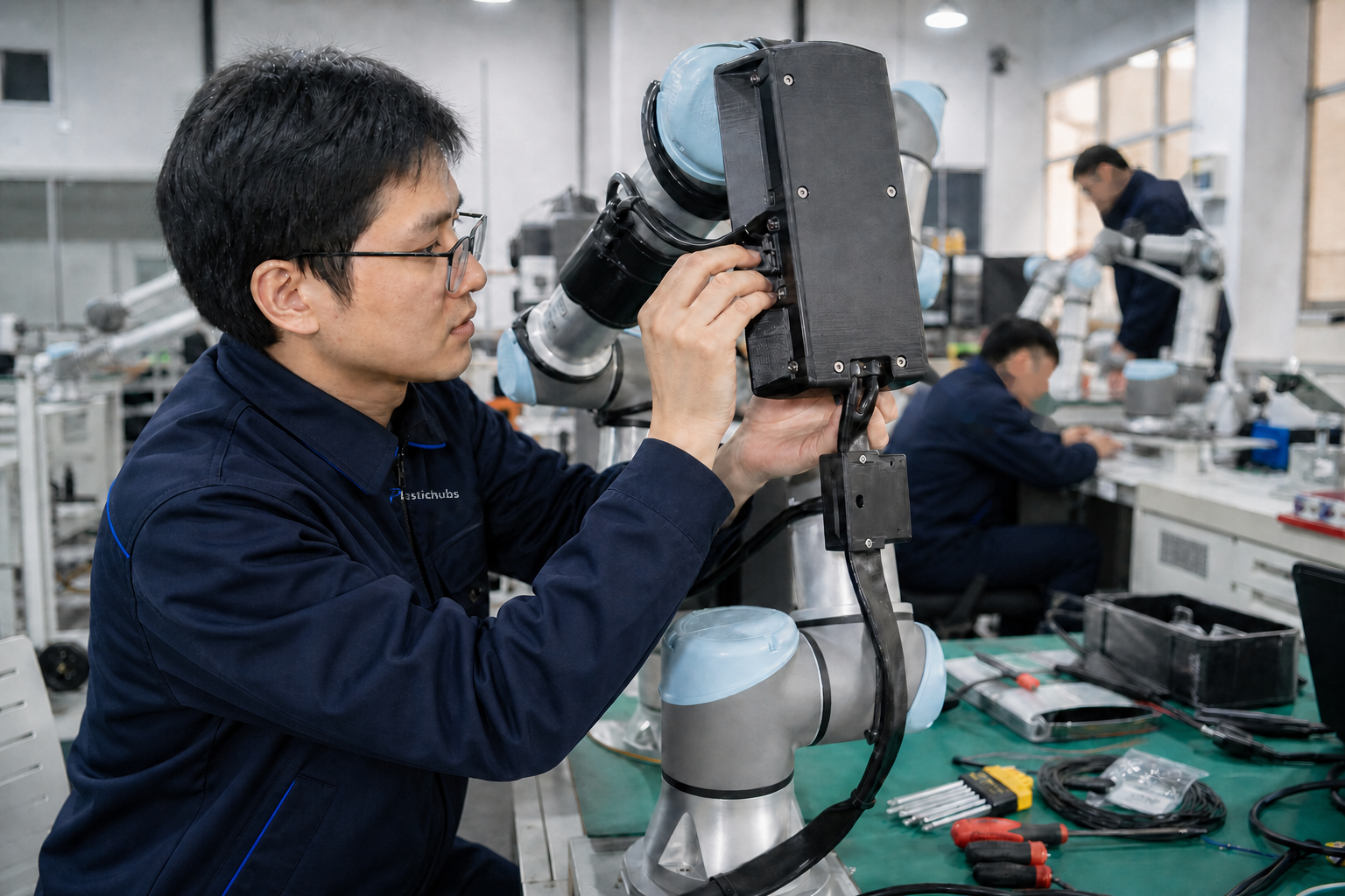
Assembled robot-arm electronics enclosure
Need: protect electronics while keeping cable and service access.
Route: functional nylon print, threaded inserts, assembly review, and dimensional checks at interfaces.
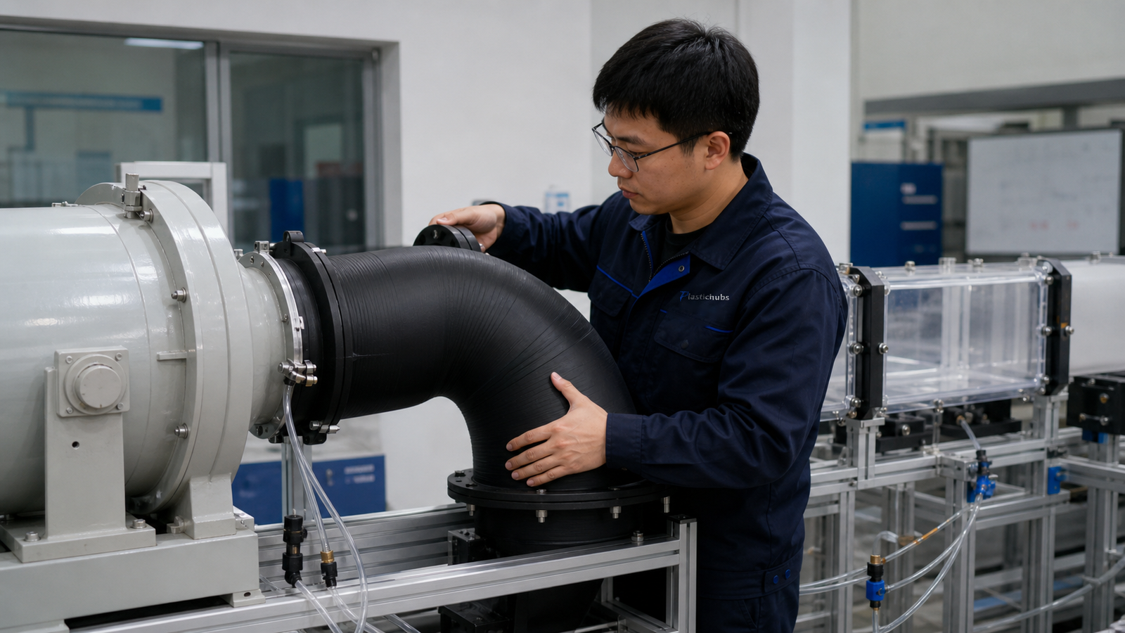
AIRFLOW
Complex duct for fit and routing evaluation
Need: confirm a curved internal path before tooling.
Route: SLS PA12, trapped-powder review, cleaning, and inspection of mating features.
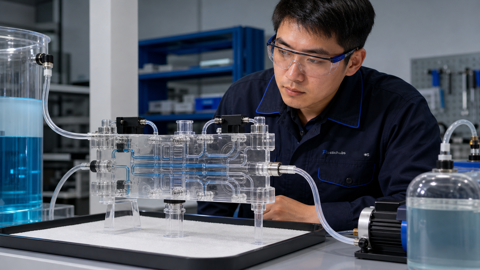
VISUAL PROTOTYPE
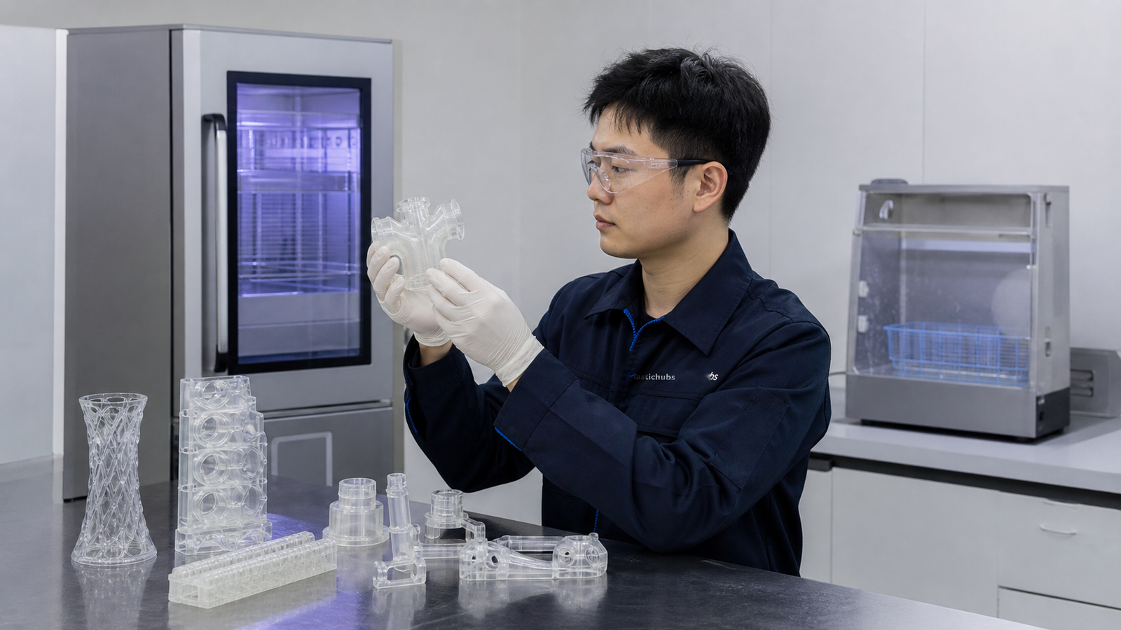
Clear manifold and cosmetic enclosure set
Need: review internal flow paths and presentation surfaces.
Route: translucent SLA resin, surface refinement, visual inspection, and protected critical interfaces.
WHY PLASTICHUBS
One plastic-focused team for printing, finishing, quality, and delivery
PlasticHubs combines in-house production capacity and qualified manufacturing partners with plastic-process selection, material options, post-processing, assembly, and drawing-based inspection.
ISO 9001ISO 13485AS9100
Start a 3D printing RFQ →3D PRINTING AND PLASTIC MANUFACTURING RESOURCES
Plan the part before requesting a quote
Use these PlasticHubs guides to compare processes, materials, finishes, and low-volume manufacturing routes.
PROCESS SELECTIONPlastic CNC Machining vs 3D PrintingCompare geometry, properties, tolerance, and volume.LOW VOLUMESmall-Batch Plastic ManufacturingChoose between printing, machining, casting, and molding.MATERIALSEngineering Plastic Material GuideUnderstand when stock plastic properties may favor CNC.FINISHINGPlastic Surface Finish TypesDefine appearance, texture, and post-processing expectations.ALTERNATIVE ROUTESVacuum Casting vs Injection MoldingCompare tooling and repeat-part options after prototyping.BUYER FAQPlasticHubs Manufacturing FAQsReview files, quotations, quality, and ordering questions.
FREQUENTLY ASKED QUESTIONS
PlasticHubs service questions
These answers describe general process behavior. Project-specific recommendations are confirmed after reviewing the part file, drawing, quantity, and intended use.
Ask an engineer →Which plastic 3D printing process should I choose?
Start with the part’s function. SLS and MJF often suit functional nylon parts and complex geometry; SLA suits detailed visual parts; FDM suits economical form checks, fixtures, and some larger parts. Operating conditions, geometry, quantity, and surface requirements can change the recommendation.
Can 3D printed plastic parts be used as end-use parts?
They can be suitable for some end-use applications, but the decision depends on load, temperature, chemicals, UV, moisture, fatigue, regulatory requirements, and the process-material combination. State the operating conditions in the RFQ.
What file format should I send?
STEP is preferred when engineering review and feature recognition matter. STL can be used for print geometry, but its mesh resolution and unit definition should be checked. A 2D drawing is useful for critical dimensions and acceptance notes.
Can printed parts be painted, dyed, smoothed, or assembled?
Post-processing options depend on the print process and material. Dyeing, painting, smoothing, insert installation, bonding, and assembly may be possible, but compatibility and dimensional effects must be reviewed for the project.
How accurate is plastic 3D printing?
Accuracy varies by process and part geometry, so one tolerance cannot cover every part. Part size, orientation, wall geometry, material, post-processing, and measurement method all affect the result. Mark critical dimensions so they can be reviewed before quotation.
When should I use CNC machining instead?
Consider plastic CNC machining when the project requires stock engineering-plastic properties, tightly controlled critical features, smooth machined interfaces, or a material that is not supported by the selected additive process.
PLASTIC 3D PRINTING SERVICES
Request printed parts, finishing, and inspection
Send the part file, quantity, intended use, material preference, finish, and critical requirements. PlasticHubs will review the available printing, finishing, and inspection options.