Most teams already understand CNC machining. The confusion starts when the same metal-focused assumptions are applied to plastic parts.
Plastic CNC machining is not just CNC machining with a softer material. Heat, clamping pressure, burr behavior, moisture movement, and post-machining stress can decide whether the part is usable.
Use plastic CNC machining when the job requires real engineering plastic behavior, controlled dimensions, and functional validation before tooling or production. It is a practical choice for custom plastic machining, CNC plastic prototypes, low-volume machined plastic parts, and pre-tooling validation.
PlasticHubs supports this work with plastic-focused DFM, material guidance, CNC milling, CNC turning, 5-axis machining, inspection, and factory-direct production support.
Plastic CNC Machining at a Glance
| Decision Area | What Engineers Need to Know | Practical Meaning |
| Process | Subtractive machining from plastic sheet, rod, plate, or block using CNC milling, CNC turning, drilling, and 5-axis machining when needed | Best for accurate functional parts made from real engineering plastics |
| Best-fit use cases | Functional prototypes, low-volume plastic parts, pilot builds, fixtures, housings, bushings, insulators, and pre-tooling validation | A highly cost-effective choice before investing in tooling |
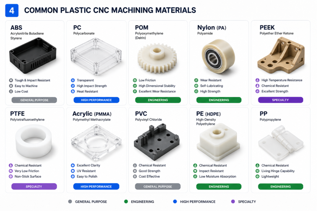
| Common materials | ABS, PC, POM/Delrin, Nylon, PEEK, PTFE, Acrylic/PMMA, PVC, PE, PP | Material choice affects tolerance, finish, heat response, moisture behavior, and dimensional stability |
| Typical part types | Machined plastic housings, brackets, spacers, bushings, rollers, covers, gears, manifolds, and electrical insulators | Works for both plastic CNC milling and plastic CNC turning |
| Key risks | Thin-wall deflection, burrs, heat buildup, clear plastic chipping, moisture movement, internal stress, and tolerance drift | Plastic machining needs plastic-specific DFM, not metal machining assumptions |
| Choose another process when | Geometry is highly organic, volume is high, molded texture is required, or flexible elastomer behavior matters | 3D printing, vacuum casting, injection molding, or silicone overmolding may be better |
Why Supplier Model Matters for CNC Plastic Parts
For plastic CNC parts, the supplier model is part of the risk profile. A broker can pass a CAD file downstream, but it may not control material handling, fixture strategy, inspection, or repeat-build consistency.
Factory-direct support gives engineering and sourcing teams a clearer path from DFM feedback to machining, inspection, and repeat orders. It reduces black-box supplier risk when the same part moves from prototype to pilot build.
That is why the quote path should do more than return a price. It should help confirm material choice, tolerance strategy, surface finish, manufacturability, and whether CNC is the right process before production starts.
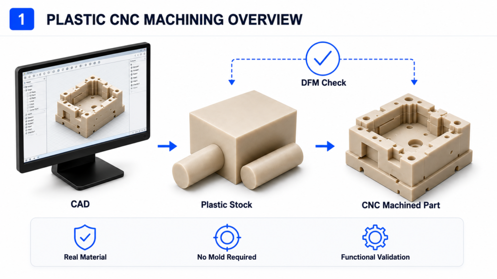
What Is Plastic CNC Machining?
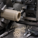
Plastic CNC machining is a subtractive manufacturing process that cuts solid plastic stock into custom parts using computer-controlled machine tools. The process can include CNC milling, CNC turning, drilling, tapping, boring, and 5-axis machining for complex plastic features.
It is different from molding because it does not require tooling. Engineers often choose it when they need accurate prototypes, low-volume plastic parts, or real engineering plastic behavior before investing in injection molding.
Plastic CNC machining is also different from metal CNC machining. Plastics have lower stiffness, lower heat resistance, different chip behavior, and higher sensitivity to clamping force, tool heat, and post-machining movement.
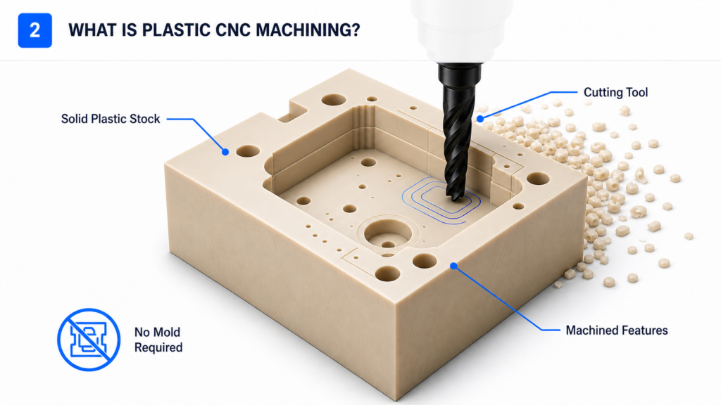
How Plastic CNC Machining Works
Step 1: Material Selection
Material selection comes first because plastics do not machine the same way. POM, Nylon, PEEK, PTFE, Acrylic, PC, ABS, and PVC each respond differently to cutting heat, tool pressure, clamping, burr formation, and finishing.
The selected material should match the part’s load, wear, friction, electrical insulation, temperature, chemical exposure, appearance, and tolerance requirement. A wrong material can create machining problems even when the CAD design is acceptable.
For example, POM is often selected for low-friction and dimensionally stable parts, while Nylon is often selected for toughness and wear resistance. PEEK is used for higher-performance applications, but it requires tighter process control because the stock material is expensive and machining mistakes are costly.
Step 2: CAD Review and DFM Feedback
A good plastic CNC project should not move directly from CAD to machining. The model should be reviewed for wall thickness, feature support, sharp internal corners, deep pockets, small holes, threads, tolerance stack-up, surface finish, and material-process fit.
DFM is project insurance. It helps identify features that may look acceptable on screen but become unstable during cutting, clamping, inspection, or assembly.
For plastic CNC machining, DFM should also check whether the part is better suited for CNC machining, 3D printing, vacuum casting, injection molding, or silicone overmolding. That process decision often matters more than the machining strategy itself.
Step 3: CAM Programming and Toolpath Control
CAM programming defines how the cutting tool removes material. For plastic, the toolpath must manage heat buildup, chip evacuation, tool engagement, burr control, and surface quality.
Sharp tools, stable cutting engagement, and proper chip removal are critical. If the tool rubs instead of cutting, the material can melt, smear, chatter, or shift dimensionally.
Toolpath strategy also affects thin features. A thin plastic wall can deflect under cutting pressure, then move again after the part is released from the fixture.
Step 4: Workholding and Deformation Control
Workholding is one of the most common sources of plastic CNC machining problems. Too much clamping pressure can deform the stock before cutting begins.
Thin walls, soft plastics, large flat panels, and flexible features need stable support. The fixture must hold the part without crushing it, bending it, or locking stress into the material.
For critical parts, fixture strategy is as important as cutting strategy. A well-programmed toolpath cannot fix a part that moves during machining or changes shape after unclamping.
Step 5: CNC Milling, CNC Turning, Drilling, and 5-Axis Machining
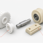
Plastic CNC milling is used for prismatic parts, flat faces, slots, pockets, housings, brackets, plates, and complex milled features. It is often the main process for custom plastic machining and CNC plastic prototype work.
Plastic CNC turning is used for round or cylindrical plastic parts. Common examples include bushings, spacers, rollers, sleeves, pins, knobs, and threaded plastic components.
5-axis plastic machining can reduce setups and improve tool access for complex parts. It is useful when the geometry requires angled features, multi-face machining, or tighter alignment across several surfaces.
Step 6: Deburring, Finishing, Inspection, and Validation
Plastic parts often need deburring after machining. Burr behavior depends on the material, tool sharpness, feature geometry, and edge requirement.
Finishing may include polishing, vapor polishing or smoothing where suitable, painting, laser marking, engraving, screen printing, or annealing when material and geometry allow. Clear plastic parts may need extra finishing control because scratches, chips, and stress marks are easy to see.
Inspection should focus on critical-to-function dimensions. Hole position, flatness, thread quality, perpendicularity, assembly datums, sealing surfaces, and mating features usually matter more than cosmetic dimensions.
Common Plastic CNC Machining Materials
| Material | Why Engineers Choose It | Main Machining Risk | Common CNC Plastic Parts |
| ABS | General-purpose prototypes, housings, covers, moderate toughness | Burrs, heat softening, surface marks | Housings, covers, brackets, fixtures |
| PC / Polycarbonate | Impact resistance, transparent or translucent parts, protective covers | Scratching, chipping, stress marks | Windows, guards, covers, protective panels |
| POM / Delrin / Acetal | Low friction, dimensional stability, wear resistance | Burr control and sharp edge quality | Bushings, gears, rollers, spacers |
| Nylon / PA | Toughness, wear resistance, sliding parts | Moisture absorption and dimensional movement | Wear pads, bushings, rollers |
| PEEK | High temperature, chemical resistance, high-performance applications | High material cost and difficult machining | Medical, aerospace, high-load parts |
| PTFE | Low friction, chemical resistance, non-stick behavior | Softness, creep, deformation during clamping | Seals, insulators, sliding parts |
| Acrylic / PMMA | Optical clarity and cosmetic parts | Brittle chipping, cracking, polishing difficulty | Transparent panels, display parts |
| PVC | Chemical resistance and industrial plastic parts | Heat control and edge quality | Chemical handling parts, panels |
| PE | Chemical resistance, toughness, low friction | Flexibility and dimensional movement | Guides, wear strips, sliding components |
| PP | Chemical resistance, lightweight parts, low-cost functional parts | Softness, burrs, clamping deformation | Chemical-resistant covers, panels, blocks, simple fixtures |
Material Selection Notes for CNC Plastic Parts
POM, Nylon, PEEK, PTFE, Acrylic, PC, ABS, PVC, PE, and PP can all be CNC machined, but they should not be treated as interchangeable plastics. The right choice depends on load, wear, friction, heat exposure, moisture, chemical contact, appearance, and tolerance requirements.
For sliding or wear parts, POM, Nylon, PTFE, and PE are common starting points. For clear covers, windows, and protective panels, Acrylic and PC are more common, but both need careful toolpath and finishing control.
For high-performance plastic parts, PEEK is often selected for demanding thermal, chemical, or mechanical conditions. Because PEEK stock is expensive, early DFM review is important before machining.
For soft or flexible plastics such as PTFE, PE, and PP, workholding and deformation control matter more than many engineers expect. These materials can move under clamping pressure, so unsupported thin features should be reviewed before production.
Plastic-Specific Machining Risks Engineers Should Watch For
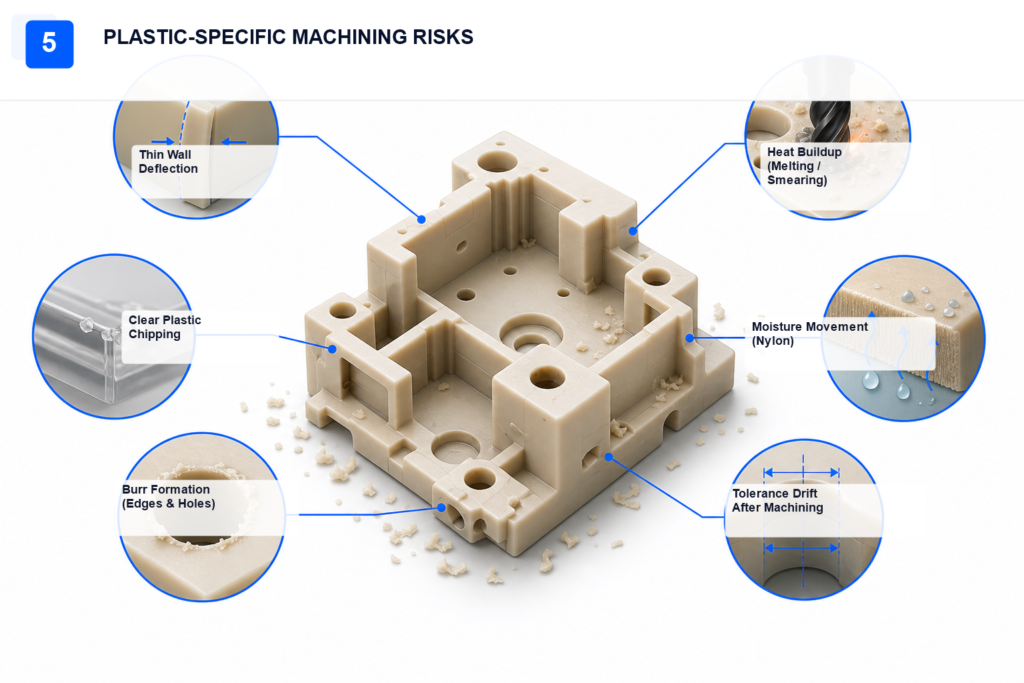
Thin-Wall Movement
Thin plastic walls can deflect during cutting. The cutter may follow the programmed path, but the wall can move away from the tool and settle into a different position after machining.
This creates a common inspection problem. The part may appear close to target during setup but fail final measurement after unclamping.
Thin walls should be reviewed early. Support features, wider tolerances, different machining sequences, or fixture changes may be needed.
Heat Buildup
Plastics usually conduct heat less effectively than metals. Heat can stay near the cutting zone and cause melting, smeared edges, poor surface finish, or dimensional drift.
Heat problems often come from dull tools, poor chip evacuation, excessive tool engagement, or rubbing. The cutter must shear the material cleanly instead of heating it.
For heat-sensitive plastics, cutting strategy has a direct effect on tolerance and appearance. Cooling, air blast, tool geometry, and feed strategy should be selected with the material in mind.
Clear Plastic Chipping
Clear plastics such as Acrylic and Polycarbonate show defects easily. Small chips, scratches, haze, stress marks, and polishing inconsistencies can make a transparent part fail cosmetic review.
Clear parts should not be treated like standard opaque functional parts. The inspection criteria must include appearance, not only dimensions.
If the part is used as a window, display cover, or protective guard, surface expectations should be defined before machining starts.
Nylon Moisture Sensitivity
Nylon can absorb moisture from the environment. This can affect dimensions after machining and after the part enters its operating environment.
The risk is higher when the part has tight fits, sliding contact, press fits, or critical hole positions. Inspection results may not fully represent how the part behaves later.
Material conditioning and tolerance planning should be discussed when Nylon is used for precision features.
PEEK Machining Difficulty
PEEK is a high-performance engineering plastic, but it is not a casual machining material. Tool wear, heat control, stock cost, and dimensional requirements all matter.
A failed PEEK part is expensive because the material itself is costly. Rework may also be difficult if the geometry is small, thin, or highly toleranced.
PEEK parts should move through DFM before production. The goal is to reduce uncertainty before material is committed to the machine.
Burrs, Threads, and Small Holes
Plastic burrs behave differently from metal burrs. Some plastics form soft burrs that fold over the edge, while others chip or crack near the feature.
Small holes, threads, thin slots, and sharp internal features are common problem areas. Tool selection, drill strategy, tapping method, and deburring access all affect quality.
Threaded plastic parts should also be reviewed for assembly load. Inserts may be better when the part needs repeated fastening or higher thread strength.
Tolerance Mismatch
Over-tight tolerances are a frequent source of cost and delay. A tolerance that looks harmless on a drawing can create fixture complexity, inspection burden, and machining risk.
The tolerance scheme should follow function. Bearing fits, sealing surfaces, assembly datums, and hole positions may need tight control, while non-critical surfaces can often accept wider tolerance.
This is where DFM helps. It aligns the drawing with the material, geometry, process, and inspection method before the part is made.
When Should You Use Plastic CNC Machining?
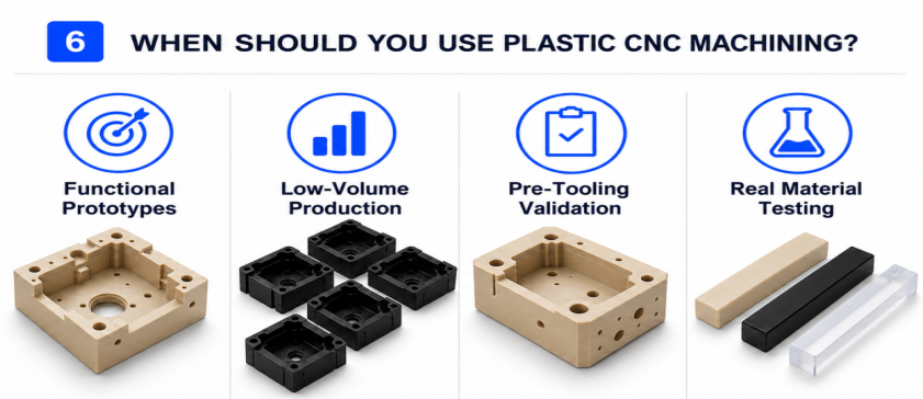
Use CNC Machining for Functional Prototypes
Plastic CNC machining is a strong choice when the prototype must behave like the final engineering plastic. This matters when the team needs to test load, friction, insulation, heat exposure, chemical resistance, fastening, or assembly fit.
3D printed prototypes can be useful early in development, but printed materials may not represent the final plastic. CNC machining from real stock gives engineers better functional feedback.
This is why CNC plastic prototype work is common before tooling. It helps teams validate the part before committing to injection mold cost and lead time.
Use CNC Machining for Low-Volume Plastic Parts
CNC machining does not require a mold, so it fits low-volume production, pilot builds, spare parts, jigs, fixtures, and bridge production. It is also useful when the design may still change.
For small batches, the tooling cost of injection molding may not be justified. CNC machining can produce functional parts directly from engineering plastic stock.
This is especially useful for NPI teams that need parts for validation builds, customer samples, field testing, or early production support.
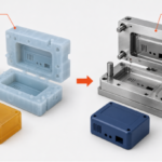
Use CNC Machining Before Injection Molding
Injection molding is efficient at scale, but tool changes can be expensive. CNC machining helps validate geometry, tolerance stack-up, assembly fit, fastening points, and material behavior before mold investment.
A machined plastic part will not replicate every molded feature, texture, gate mark, or production behavior. It can still reveal many design issues before tooling starts.
For pre-tooling validation, CNC machining is often used to reduce design uncertainty. The goal is not to avoid molding forever; the goal is to enter molding with fewer unresolved risks.
Use CNC Machining When Real Material Behavior Matters
Real plastic stock matters when the part must be tested under mechanical, thermal, electrical, chemical, or wear conditions. Printed resin and casting resin may not match the target engineering plastic.
CNC machining supports functional validation in materials such as POM, Nylon, PEEK, PTFE, PC, Acrylic, ABS, PVC, PE, and PP. This makes it valuable when the test result depends on material behavior.
If the question is only ‘Does the shape look right?’, 3D printing may be enough. If the question is ‘Will the part work?’, plastic CNC machining often provides better evidence.
Plastic CNC Machining vs 3D Printing, Vacuum Casting, and Injection Molding
| Process | Best For | Strength | Limitation | Choose Plastic CNC Machining Instead When |
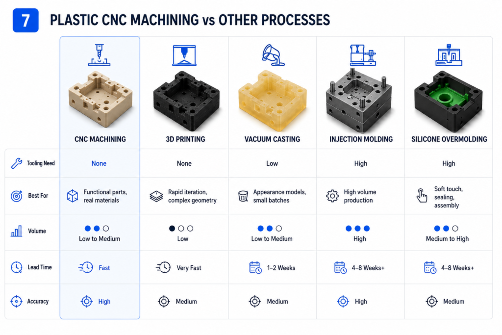
| Plastic CNC Machining | Functional prototypes, low-volume parts, engineering plastic components | Real stock material, good dimensional control, no mold cost | Less efficient for very high-volume production or highly organic geometry | Material behavior, tolerance, and functional validation matter |
| 3D Printing | Early design iteration, complex shapes, visual models | Fast geometry iteration and design freedom | Printed materials may not match final engineering plastics | You need real plastic stock and tighter functional validation |
| Vacuum Casting | Small batches with molded-like appearance | Good for cosmetic prototypes and soft tooling runs | Polyurethane behavior may not match the target production plastic | You need specific engineering plastic properties |
| Injection Molding | High-volume production with stable design | Best unit economics at scale | Tooling cost, tooling lead time, mold correction risk | The design is not validated or the volume is still low |
| Silicone Overmolding | Soft-touch, sealing, grip, or elastomeric features | Useful for multi-material soft features | Not a replacement for rigid plastic CNC parts | The part needs rigid engineering plastic geometry |
Plastic CNC Machining vs 3D Printing
3D printing is often better for early design iteration, complex shapes, and quick visual models. It can produce geometry that is difficult or impossible to machine.
Plastic CNC machining is better when the part needs real stock material, tighter functional dimensions, smoother machined features, or better validation of final-use behavior.
Use 3D printing when geometry speed matters most. Use CNC machining when material and function matter more.
Plastic CNC Machining vs Vacuum Casting
Vacuum casting is useful for small batches with molded-like appearance. It can be suitable for sales samples, cosmetic prototypes, and short runs where polyurethane properties are acceptable.
Plastic CNC machining is better when the part must use a specific engineering plastic. POM, Nylon, PEEK, PTFE, PC, Acrylic, ABS, PVC, PE, and PP each provide material behavior that casting resin may not match.
Use vacuum casting when molded-like appearance and batch replication matter. Use CNC machining when material behavior and dimensional validation are the priority.
Plastic CNC Machining vs Injection Molding
Injection molding is usually the right choice when the design is stable and the volume supports tooling. It provides strong unit economics at scale and consistent production once the mold is validated.
Plastic CNC machining is better before the design is frozen. It avoids mold investment and supports faster design changes during validation.
Many teams use both processes in sequence. CNC machining supports prototype and pilot validation, then injection molding takes over when design and volume are ready.
Plastic CNC Machining vs Silicone Overmolding
Silicone overmolding is used for soft-touch surfaces, seals, grips, gaskets, and multi-material features. It is not a replacement for rigid CNC plastic parts.
Plastic CNC machining is better for rigid engineering components with controlled geometry. Silicone overmolding is better when the function depends on elastomeric behavior.
Some projects need both. A rigid CNC plastic component may be used to validate the base geometry before overmolding or production tooling is planned.
When Plastic CNC Machining Is Not the Right Process
High-Volume Parts with Stable Design
If the design is frozen and the volume supports tooling investment, injection molding is usually more suitable. CNC machining can become less efficient when the same part must be made in very large quantities.
CNC machining can still support early builds, spare parts, or bridge production. It should not be forced into a role where molding is clearly the better long-term process.
Highly Organic Geometry or Internal Lattice Structures
CNC machining requires tool access. If the part has internal channels, lattice structures, sculpted organic surfaces, or geometry that cannot be reached by cutting tools, 3D printing may be better.
This is a geometry-driven decision. A part can be simple to print but difficult to machine if tool access is poor.
Molded Texture or Production Surface Replication
CNC machining can create accurate parts, but it does not fully replicate every molded texture, parting line, gate mark, or molded surface behavior. If production appearance is the main concern, injection molding or vacuum casting may be more appropriate.
This matters for consumer-facing parts. A prototype that passes dimensional inspection can still fail visual review if the surface expectation was never defined.
Soft Elastomeric Parts
Rigid plastic CNC machining is not the right process for soft-touch, gasket-like, rubber-like, or highly flexible parts. Silicone overmolding, urethane casting, or elastomer-specific processes may be better.
The decision should start with function. If the part must seal, flex, grip, or compress repeatedly, the material and process should match that behavior.
Plastic Machining Tolerances: What Engineers Should Know
Plastic machining tolerances depend on part geometry, material behavior, wall thickness, feature size, workholding, toolpath, surface finish, and inspection method. A rigid POM spacer and a thin PTFE seal do not behave the same way under cutting pressure.
Our CNC machining capability data supports CNC milling tolerances as tight as ±0.01 mm and CNC turning tolerances as tight as ±0.005 mm. For plastic parts, the practical tolerance plan should still be tied to the function of the part.
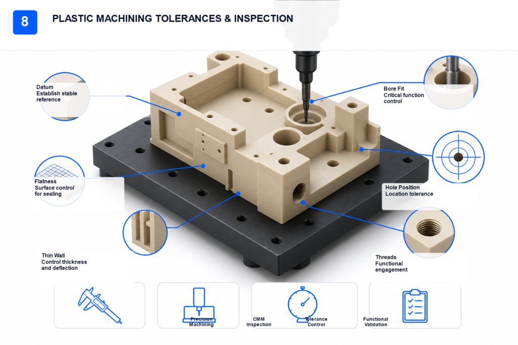
The best approach is to assign tight tolerances only where they matter. Functional interfaces, bearing fits, hole positions, sealing surfaces, and assembly datums should receive priority.
| Tolerance Area | Engineering Guidance |
| Bearing fits | Define material, mating part, load, and operating temperature |
| Hole position | Control datums and inspection method |
| Flatness | Review wall thickness, stock stress, and clamping |
| Threads | Check assembly load and repeat fastening requirements |
| Clear surfaces | Define both dimensional and cosmetic requirements |
| Thin walls | Review support, deformation, and inspection strategy |
| Non-critical surfaces | Use wider tolerances when function allows |
For NPI and pilot builds, inspection should match the part risk. CMM verification is valuable when the part has tight positional requirements, multiple setups, datum relationships, or critical assembly features.
How DFM Reduces Plastic CNC Machining Risk
DFM checks whether the CAD model can become a stable physical part. For plastic CNC machining, it should review material choice, wall thickness, feature support, tolerance strategy, tool access, workholding, surface finish, and inspection needs.
A good DFM review prevents avoidable re-quotes, failed prototypes, material waste, and delayed validation cycles. It also helps decide whether CNC machining is the correct process before production starts.
PlasticHubs connects DFM feedback with plastic-focused machining execution. This helps engineering teams solve problems before the part reaches the machine.
Plastic CNC DFM Checklist
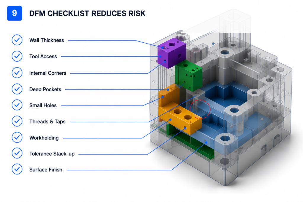
| DFM Check | Why It Matters |
| Thin walls | Reduces deflection and post-machining movement |
| Deep pockets | Checks tool reach, chatter, and internal corner limits |
| Sharp internal corners | Prevents impossible or high-cost toolpath requirements |
| Small holes and threads | Reduces breakage, burrs, and assembly failure |
| Clear plastic surfaces | Controls chipping, scratching, and polishing expectations |
| Nylon and moisture exposure | Reduces dimensional surprises after machining |
| PEEK machining plan | Reduces material waste and quality risk |
| PTFE clamping strategy | Reduces deformation and creep-related issues |
| Tolerance stack-up | Keeps tight tolerances on functional features only |
| Surface finish | Aligns machining output with cosmetic or functional needs |
| Production scaling | Checks whether CNC should remain the process or move to molding |
How to Choose a Plastic CNC Machining Supplier
Check Whether the Supplier Understands Plastic, Not Only CNC
A supplier that mainly machines metal may not automatically understand plastic-specific risks. Ask how they handle thin-wall support, clear plastic polishing, Nylon moisture behavior, PEEK machining, PTFE deformation, burr control, and plastic inspection.
The supplier should be able to discuss material behavior before quoting. If every plastic is treated the same way, the project risk is higher.
Avoid the Broker Trap: Check Whether the Supplier Is Factory-Direct
Brokerage and marketplace models can add communication layers, supplier switching risk, and cost opacity. For engineering plastic parts, that risk increases when DFM feedback, material handling, inspection, and repeat builds are handled by different parties.
A factory-direct model gives engineers clearer control over DFM feedback, scheduling, quality review, and repeat production. It also reduces the chance that the buyer does not know who is actually making the part.
For NPI projects, this matters. The same supplier should understand the prototype, pilot build, inspection requirement, and later production path.
Check Whether They Support Prototype-to-Production Work
A strong supplier should support 1-piece prototypes, pilot builds, low-volume production, repeat orders, material selection, finishing, inspection, and process transition to injection molding when volume increases.
This reduces supplier switching. It also helps keep design history, DFM decisions, and inspection knowledge in one manufacturing workflow.
For engineers, that continuity can be more valuable than a one-time low quote.
Check Whether Quality Systems Are Visible
Quality should not be a vague promise. Look for ISO-backed quality systems, CMM verification, material control, inspection reports, and clear communication around critical dimensions.
For plastic parts, quality control should cover more than final dimensions. It should also consider burrs, surface finish, cosmetic expectations, deformation, and assembly fit.
How PlasticHubs Reduces Plastic CNC Machining Risk
PlasticHubs supports plastic-focused CNC machining, plastic CNC milling, plastic CNC turning, and 5-axis plastic machining for custom engineering plastic parts.
The manufacturing workflow connects instant quote access, AI/DFM feedback, factory-direct execution, self-operated manufacturing resources, audited production capacity, quality engineering, CMM verification, ISO-backed quality systems, no-MOQ prototype support, CNC lead times from 3 days, and prototype-to-production support.
This structure gives engineering teams more than machining capacity. It helps them reduce wrong-process decisions, plastic-specific machining defects, broker opacity, supplier switching, and delayed validation cycles.
Technical FAQ
What is plastic CNC machining?
Plastic CNC machining is a subtractive manufacturing process that cuts solid plastic stock into custom parts using CNC milling, CNC turning, drilling, tapping, boring, and related operations.
It is used when engineers need real engineering plastic properties, controlled dimensions, and functional validation before tooling or production.
What plastics can be CNC machined?
Common CNC machining plastics include ABS, PC, POM/Delrin, Nylon, PEEK, PTFE, Acrylic/PMMA, PVC, PE, and PP.
Each material has different machining behavior, so material selection should be reviewed before quoting or production.
Is CNC machining plastic better than 3D printing?
Plastic CNC machining is better when the part needs real plastic stock material, tighter functional dimensions, and better validation of final-use behavior.
3D printing is often better for rapid geometry iteration, complex organic shapes, and early visual models.
What tolerances can plastic CNC machining hold?
Our CNC machining capability data supports CNC milling tolerances as tight as ±0.01 mm and CNC turning tolerances as tight as ±0.005 mm.
For plastic parts, the final tolerance plan should be matched to the material, geometry, wall thickness, feature size, workholding, and inspection method.
Can clear plastic parts be CNC machined?
Yes. Acrylic and Polycarbonate can be CNC machined, but clear parts need careful tool selection, chip control, handling, polishing, and stress control.
Surface expectations should be defined before machining starts.
When should I choose injection molding instead of plastic CNC machining?
Choose injection molding when the design is stable, production volume is high, and tooling investment is justified.
Choose CNC machining when the design is still being validated, volume is low, or real material testing is needed before mold production.
What is the difference between plastic CNC milling and plastic CNC turning?
Plastic CNC milling is used for prismatic parts with pockets, slots, flat faces, holes, and complex milled features.
Plastic CNC turning is used for round or cylindrical parts such as bushings, spacers, rollers, sleeves, pins, and threaded plastic components.
Get Plastic CNC Machining Feedback Before Production
Plastic CNC machining is often the right choice when engineers need real material behavior, functional validation, and controlled dimensions before tooling or production. The main risk is assuming that a plastic part will machine like metal or that every plastic will behave the same way.
Upload your CAD file to get an instant quote and DFM feedback before machining. PlasticHubs helps engineers confirm material choice, tolerance strategy, surface finish, and manufacturability before prototype, pilot build, or production.