PTFE machined parts can work well when a part needs chemical resistance, low friction or electrical insulation. PTFE also has a tradeoff: it is softer and less rigid than many other engineering plastics. A thin part may bend while it is held in a CNC machine. A loaded part may change shape later, even if it passed its first inspection.
That does not rule out PTFE. It means the material, part shape and inspection plan need to fit the job. This guide explains what to check before ordering custom PTFE parts and what to send a supplier for a useful quote.
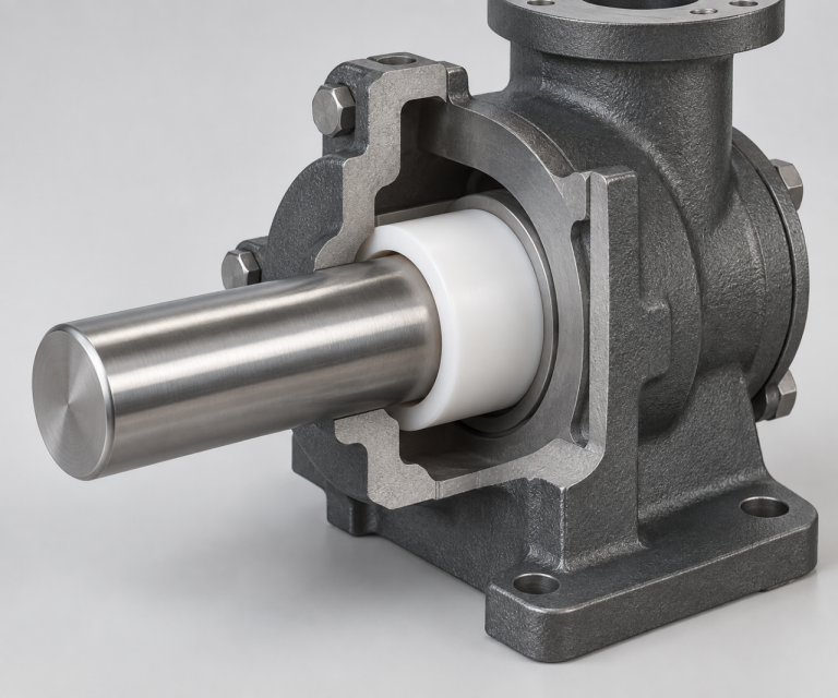
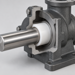
Illustration of a PTFE bushing between a shaft and housing.
When Is PTFE a Good Choice for a Machined Part?
PTFE is often worth considering for seals, valve seats, bushings, sliding parts and electrical insulators. The best choice depends on what the part does in service. A seal needs a sound contact surface. A bushing needs a workable fit with the shaft. An insulator needs the right electrical properties for its setting. These needs can point to different PTFE grades and different ways to inspect the finished part.
For custom shapes, plastic CNC machining can turn PTFE stock into parts made to a drawing. Before machining starts, the supplier needs to know which features matter most and how the part will be used.
Where PTFE is useful
PTFE is useful when its low friction, broad chemical resistance or electrical insulation solves a clear problem. It also takes up very little moisture. For example, a sliding pad may benefit from low friction, while a seal in chemical equipment may need resistance to a specified fluid. The application still needs a grade check: naming the material family alone does not prove that a finished part will work in every chemical, temperature or load condition.
Where PTFE needs extra care
PTFE is less rigid than many common machining plastics. If a part must carry a load for a long time, keep a tight press fit (a connection held together by pressure) or hold a thin wall in shape, the design deserves extra review. PTFE can slowly change shape under a steady load. This is often called creep or cold flow. A small change can matter if the part seals against another surface or must slide with a set clearance.
The answer may be a thicker wall, a different fit, a modified or filled PTFE grade, or another plastic. Which option helps depends on the part and its working conditions. If PTFE is one of several candidates, compare other CNC-machinable plastics before the drawing is fixed.
Which PTFE grade and stock should you ask for?
A drawing that says only “white PTFE” leaves an important choice open. A grade is a specific version of the material. Virgin PTFE means PTFE without added fillers. It may suit a part where that unfilled composition, low friction or electrical behavior is important. It does not, by itself, prove a special purity level. If contamination limits matter, name the required grade and documents.
Modified or filled PTFE may be considered when wear, creep or shape change is a concern. A filler can improve one property while changing another, including electrical or chemical behavior. Tell the supplier what problem the grade needs to solve instead of asking for “the strongest PTFE.”
The starting shape matters too. Stock is the piece of material before it becomes a finished part. PTFE stock may come as rod, tube, sheet or a molded blank. A ring cut from tube stock may need a different setup from a flat part cut from sheet. If your project requires a certain stock form or material record, put that in the request. If it does not, share the part drawing and working conditions so the supplier can review the options.
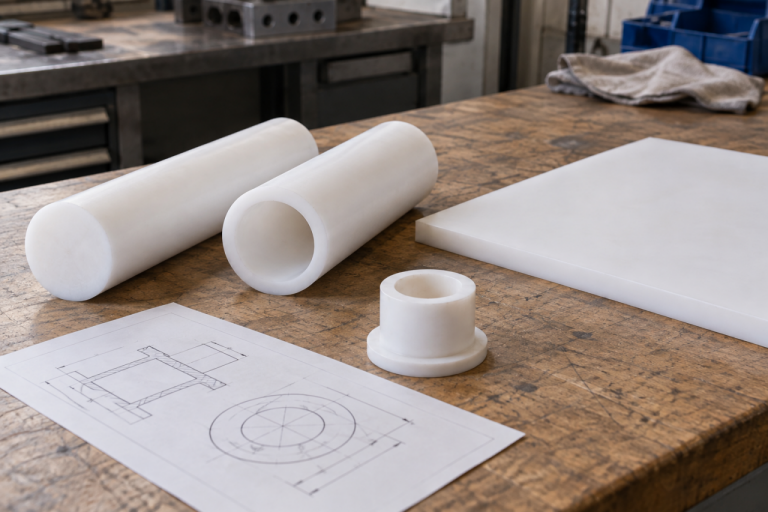
PTFE rod, tube and sheet stock can lead to different machining setups.
Why Can PTFE Change Shape During and After CNC Machining?
PTFE can be turned, milled and drilled, but the force used to hold and cut it can affect the result. A clamp can squeeze a soft part. A cutting tool can push a thin wall. Heat from machining can also change the dimensions. Once the clamp is released, the part may move toward its free shape. A measurement taken while the part is still held may therefore differ from one taken later.
Slow change under load is another concern. A bushing might measure correctly on the inspection bench but lose some of its intended clearance after assembly. A seal may change where it contacts a mating face. These are reasons to tell the supplier how the part will be installed and loaded, not reasons to assume that every PTFE part will fail.
To reduce these risks, machining and inspection usually need attention in five places:
- Hold the part without squeezing it. Wider contact areas, suitable jaws or a custom support may help keep a flexible shape stable.
- Use a sharp cutting tool. A dull edge can push or smear PTFE instead of cutting it cleanly.
- Clear chips from the cut. Chips left near the tool can add heat and mark the surface.
- Choose the order of operations carefully. Some parts benefit from rough cutting, release from the fixture and a later finishing cut.
- Agree on when to measure. State whether the part is checked while held, after release or in a defined assembly condition.
The exact cutting settings and sequence depend on the grade, stock, size and shape. A thick ring and a large thin plate will not respond to the same setup in the same way. Ask for a review of your drawing rather than applying one advertised tolerance to every PTFE part.
Design PTFE Parts Around the Features That Matter
The easiest way to make a PTFE drawing useful is to show what each critical feature does. A seal may depend on one contact face and one groove. A bushing may depend on its bore and its clearance around a shaft. The rest of the shape may allow more room for variation. Marking that difference helps the supplier spend machining and inspection effort where it affects the part’s function.
Thin walls, deep slots, long sleeves and wide flat sections need special attention because they can move when held or cut. A wall that looks thick enough in a 3D model may still be hard to support in the machine. If the design can change, the supplier may suggest a thicker wall, a shorter unsupported length or a different order of machining steps.
PTFE can also have machined threads, but a thread needs to be judged by how it will be used. Will it be tightened once or taken apart often? Will it carry a steady load? Is there enough material around it? A lightly loaded adjustment feature and a connection that is opened every week may call for different designs. Share the mating part and the assembly method before the thread is approved.
Tool access affects small corners and deep grooves. A round cutter cannot make a perfectly sharp inside corner. A deep narrow groove can make chip removal and inspection harder. A sealing edge may need careful handling after the cut. The broader plastic CNC machining tolerances and DFM guide explains these design issues; PTFE adds more reason to consider support and measurement conditions.
On the drawing, separate the features into three groups:
- Parts that make it work: sealing faces, sliding surfaces, bores or electrical gaps.
- Parts that make it fit: hole positions and contact points used during assembly.
- General shape: dimensions that describe the part but do not need the same tight control.
This does not mean general dimensions can be ignored. It tells the supplier which features deserve the closest review and which may have room for a practical manufacturing choice.
Tell the Supplier How the Part Will Be Checked
Words such as “tight tolerance,” “smooth finish” and “no deformation” leave too much room for interpretation. A useful drawing identifies the critical feature, states the needed result and explains how to check it. For a PTFE part, it can also matter whether the measurement is taken before or after the part is released from the fixture.
Use this table as a prompt when preparing the drawing or request for quotation (RFQ):
| If the part needs… | Include this information | Ask the supplier… |
| A fit with another part | Mating part size, critical diameter and how the fit works | Will the PTFE part be measured free or held in a defined fixture? |
| A seal or valve contact | The contact face, groove and sealing function | Which surfaces and dimensions control the seal? |
| A thin wall or flexible flange | Wall size, unsupported length and assembly force | How will this feature be held and measured? |
| Chemical or temperature resistance | The fluid, relevant concentration, temperature and exposure time | Does the proposed grade fit these conditions? |
| A sliding or wear surface | Load, movement, mating material and lubrication | Should virgin, modified or filled PTFE be reviewed? |
| Inspection records | Critical dimensions, checking method and documents needed | Which checks happen after the final machining step? |
The table cannot give one tolerance that fits every part. What is practical depends on the grade, size, wall thickness, shape, machining method and how the part is measured. A small, thick ring and a large, thin plate pose different problems. Ask the supplier to confirm the critical dimensions for your specific drawing.
Measurement can change the apparent result. A measuring tool may press on a flexible face. A fixture may hold a warped part flat. A part can also move after it is released or as its temperature changes. If the part must work in a certain assembled position, define that condition. If it must meet dimensions while free, say that instead.
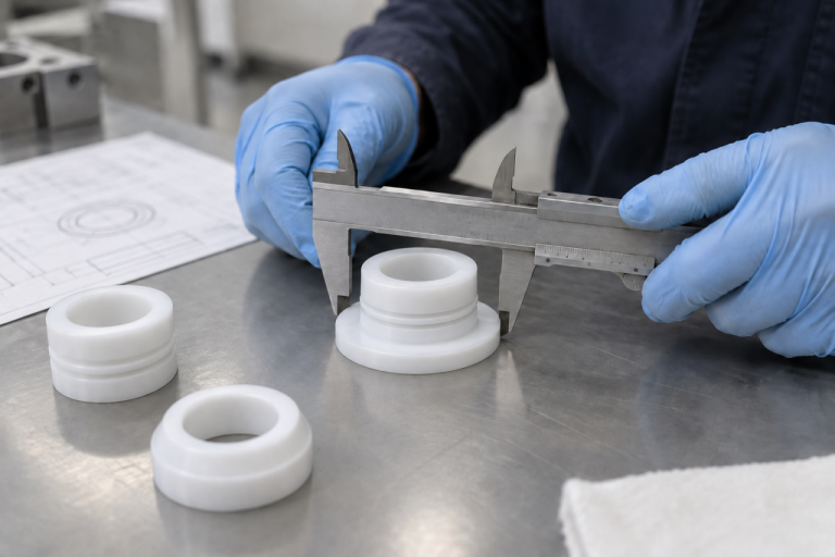
Illustrative inspection scene: a stepped PTFE bushing rests freely as its flange diameter is checked.
For a first prototype, check the inspection plan as well as the machining result. A trial part may show that a measurement is hard to repeat or that an assembled fit matters more than a free diameter. You can then agree on a clearer check before ordering a larger batch. This focuses the drawing on performance; it does not require relaxing every tolerance.
Mark surface requirements by area. A sealing face, a sliding face and a hidden clearance surface may need different finishes. State which area matters and why. That helps prevent extra finishing work from changing an edge or dimension that controls the fit.
Send a Quote-Ready PTFE Package
A useful quote starts with a useful set of project details. Send a 3D model and a drawing if you have both. The model shows the shape; the drawing shows the grade, critical dimensions and conditions that the model cannot explain on its own.
Include:
- the PTFE grade you need, or the conditions the material must handle;
- the quantity, prototype needs and likely repeat orders;
- the dimensions that control fit or function, plus mating part details;
- the chemicals, temperature, load, movement and assembly method;
- sealing, electrical, wear or surface requirements;
- inspection reports, material documents and packaging needs;
- any feature you are willing to change after design review.
It helps to say what is fixed and what can change. For example, you may need one grade but have room to make a wall thicker. Or the outside shape may be fixed while the attachment method is open. That gives the supplier a clear way to suggest a more stable part.
Grade, stock availability, part size, setups and inspection work can all affect cost. A tight limit on a dimension that has no effect on the part’s job may add work. The actual price and any design change must still be reviewed against the drawing. A generic cost or savings promise would not be useful here.
PlasticHubs can review the material, part shape, machining steps and inspection needs together. Send your PTFE project requirements for a project-specific review and quote. Include the drawing or CAD file, grade or working conditions, quantity and critical dimensions. You can also include the mating part and any documents you need with the finished parts.
PTFE Machined Parts FAQ
Can PTFE machined parts hold tight tolerances?
PTFE can be machined to controlled dimensions, but the useful tolerance depends on the part. Grade, size, wall thickness, clamping and measurement all matter. Mark the dimensions that control fit or function and ask the supplier to confirm what is practical for that drawing and inspection method.
Should I choose virgin or filled PTFE?
Start with what the part must do. Virgin PTFE is unfilled and may suit a job where its low friction or electrical behavior matters. A modified or filled grade may help with wear or slow shape change under load, but it can change other properties too. Share the working conditions and request the documents your project needs.
Can a PTFE part have thin walls or threads?
Yes, if the design and use allow it. Thin walls may bend under clamping or cutting force. Threads may change shape under repeated or steady load. Show the mating part, how often the connection will be used and how much load it carries so the supplier can review the design.
What should I send for a PTFE machining quote?
Send the 3D model and drawing, expected quantity, PTFE grade or working conditions, critical dimensions and mating part details. Add chemical, temperature, load and movement conditions, plus your inspection and document needs. State which design features can change. These details help the supplier review the part and prepare a more useful quote.