
01
Thin-wall Design & Grade Selection
Select the formulation against flow length, fine partitions and thermal exposure. Compare high-flow, low-warpage and reinforced systems separately rather than treating one LCP grade as every product.
Built for production.
Take your design from tooling to repeat production of custom plastic parts.
Manufacturing Capabilities
Plastic Injection MoldingCustom plastic parts for production Tooling & Design SupportPrepare your part design for tooling High-Volume ProductionPlan repeat runs around your delivery needsMaterials & Finishes
Made for smaller runs.
Produce resin parts with silicone molds for design validation and small batches.
Small-Batch Capabilities
Vacuum CastingResin parts made with silicone moldsLow-Volume ProductionFrom trial parts to small-batch deliveryAppearance & Fit ChecksPrepare multiple parts for product checksMaterials & Finishes
Other Services
Machining, printing, and supporting services for specific part needs.
Materials & Finishes
Explore material performance and appearance options separately.
Explore Materials & Finishes
Injection Molding Materials
Choose molding materials for strength, heat resistance and appearance.
Manufacturing Knowledge
Find articles, answers, and case studies to help prepare your project.
Start with your part requirements.
Contact PlasticHubs for help with quotes, files, delivery, and orders.
Files, Orders & Delivery
Industries
Explore manufacturing options for your product application.
Start with your manufacturing needs
From tooling to production of plastic parts.
Small batches of resin parts made with silicone molds.
Start with your design, material, and quantity.
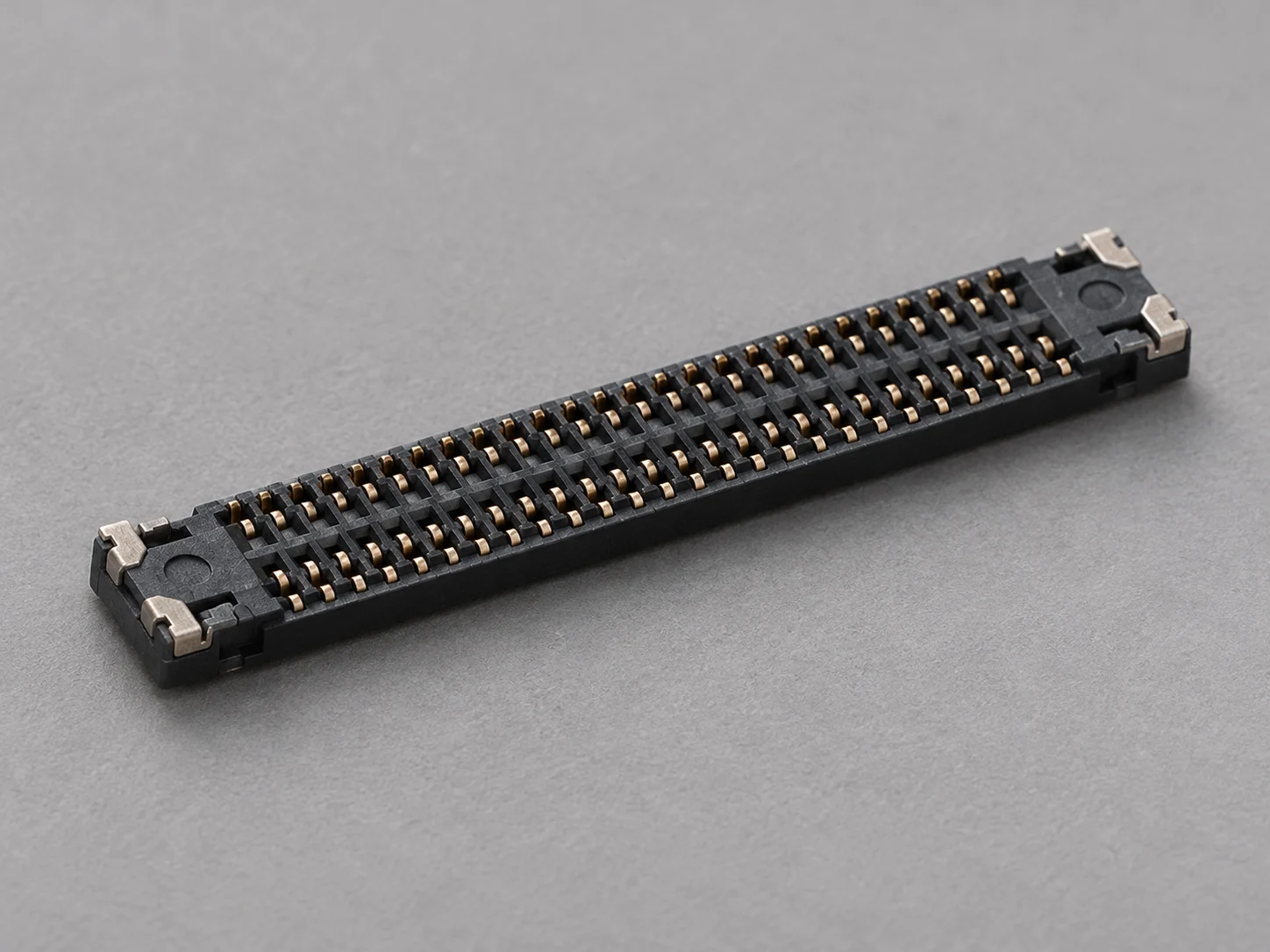
Plan LCP injection molding for thin-wall connectors and precision electrical components. Review grade, flow orientation and weld lines with tooling so fine features, critical dimensions and assembly requirements work together.
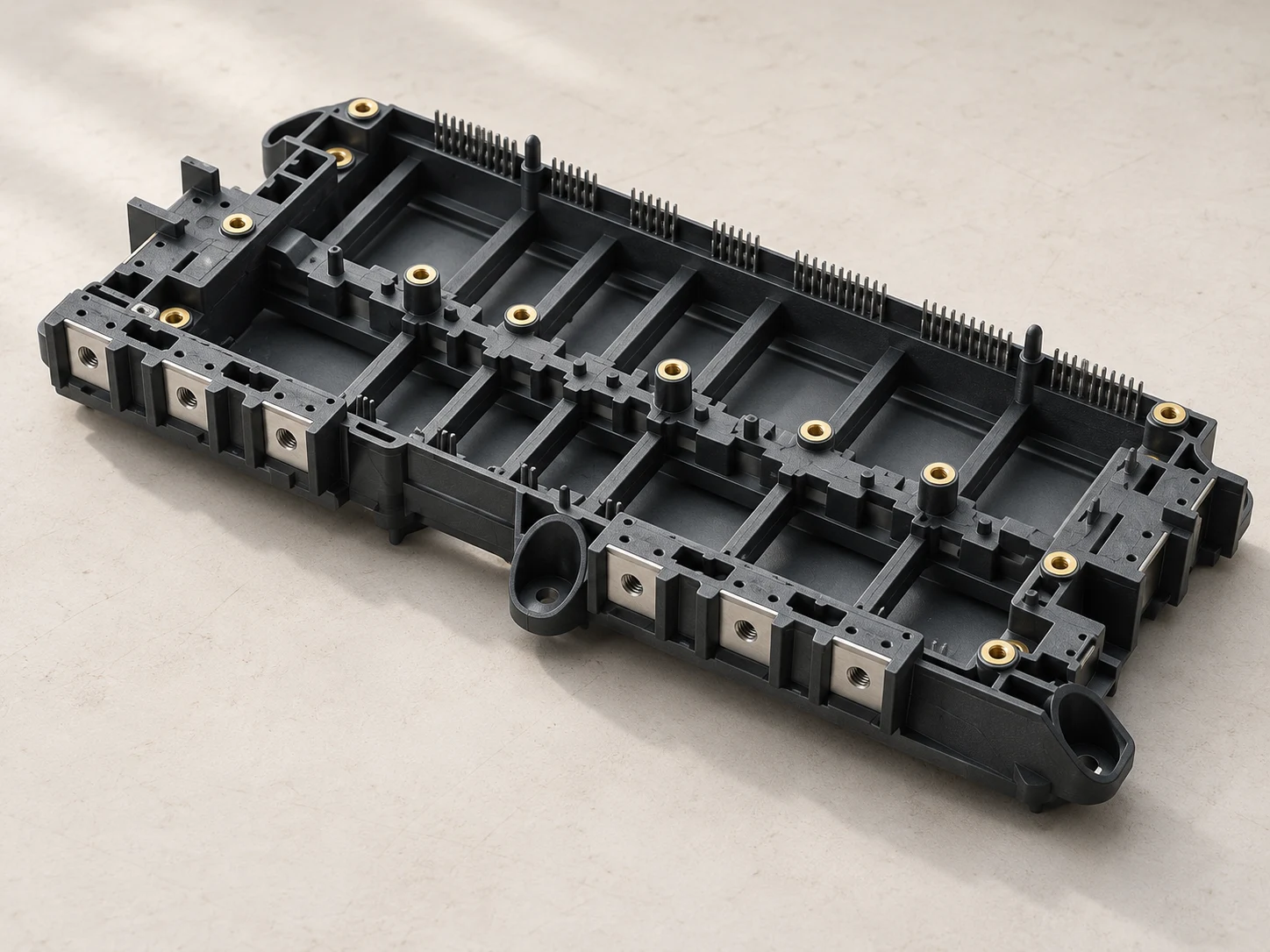
Share wall sections, contact or hole layouts, assembly datums and thermal exposure. For connector or switch components, include the applicable insulation, mating-cycle and solder-reflow validation requirements.
Discuss your project ↗Select the formulation against flow length, fine partitions and thermal exposure. Compare high-flow, low-warpage and reinforced systems separately rather than treating one LCP grade as every product.
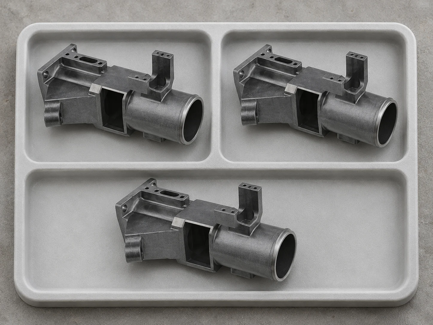
Prepare resin to its grade guidance, reviewing filling speed, tool thermal condition and venting together. Check short shots, flash, weld lines and dimensions during trials before setting the production baseline.
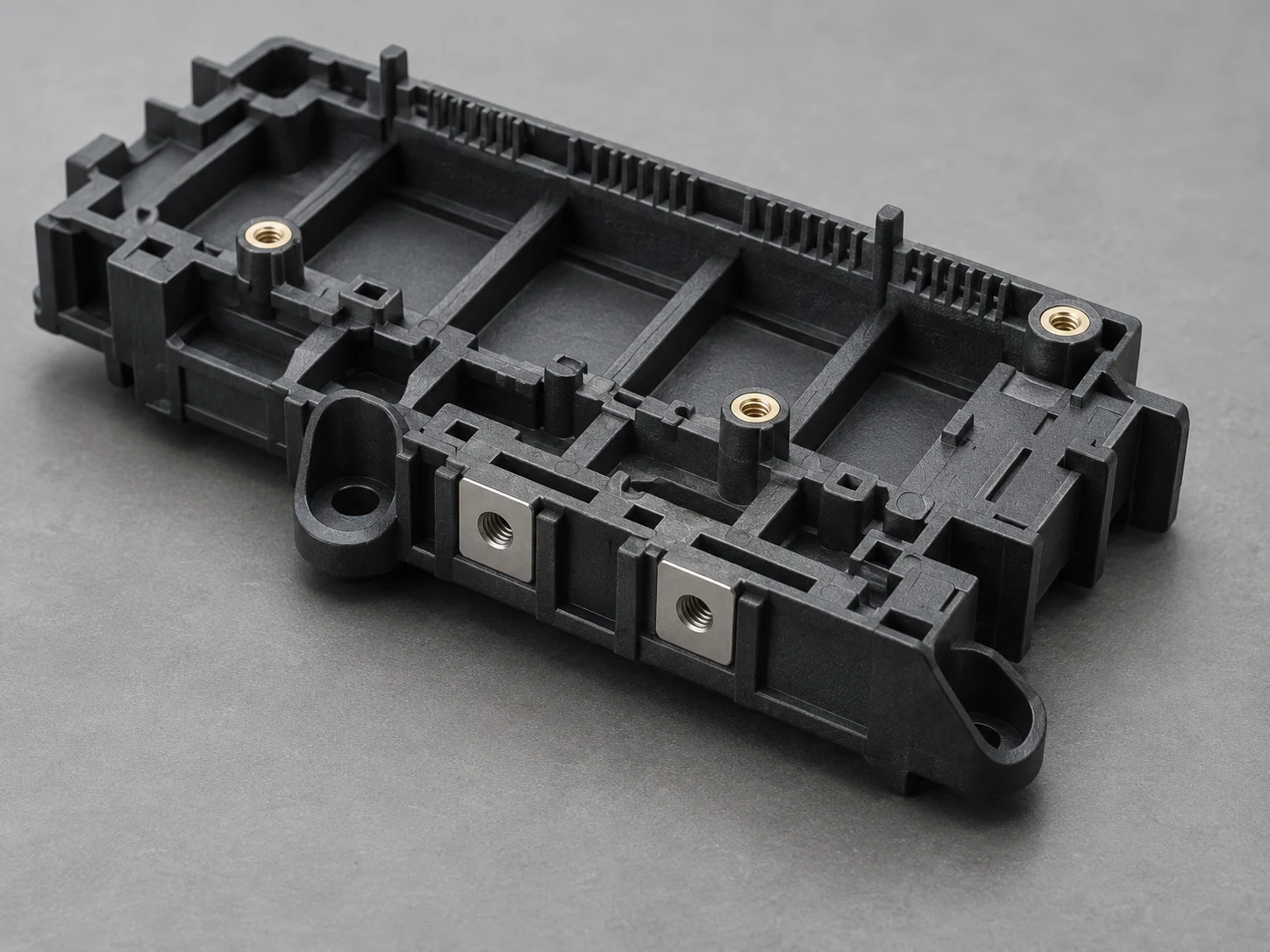
Define datums and acceptance dimensions around ports, ribs and fastening areas. Review interfaces for loading, temperature and fit, confirming function against project drawings and samples.
Share drawings, quantity and thin-wall, thermal and assembly requirements.
| Project focus | Review scope |
|---|---|
| Grade and function | Distinguish reinforced, high-flow and low-warpage formulations against thermal exposure, electrical function and assembly needs. |
| Resin preparation and process guidance | Follow the selected grade’s drying and material-handling guidance. Confirm melt and tool conditions with the supplier rather than using melting temperature as a process setting. |
| Thin-wall flow and orientation | Review flow length, gates, fine cores and venting, focusing on orientation, directional shrinkage and loaded weld lines. |
| Contacts and dimensional control | Define contact location, coplanarity, mating and fastening datums, assessing metal/polymer fit through thermal cycling. |
| Samples and functional validation | Check dimensions, mating, insulation and relevant thermal histories on actual parts, keeping material-specimen data separate from product acceptance criteria. |

Coordinate wall sections and transitions with the filling path, avoiding abrupt thickening and sharp corners. Verify fine partitions, slender cores and long flow paths for the grade and tool rather than imposing one universal minimum wall.
Flow orientation gives LCP directional properties and shrinkage. Position gates around contact location and coplanarity, assessing parallel and transverse dimensions separately and validating the cooled shape.
Holes, terminals and multiple gates can divide flow and form weld lines. Check meeting regions against mating, clip and fastening loads rather than treating weld lines only as an appearance issue.
High-flow thin-wall filling requires coordinated venting, parting-line fit and slender-core support. Select draft and ejection for depth, texture and local geometry to limit contact-interfering flash and damage to fine walls.
Define contact, dimensional and cosmetic acceptance areas before choosing tool surfaces. Formulation, flow orientation and weld lines affect molded appearance; confirm the result with samples of the selected grade.
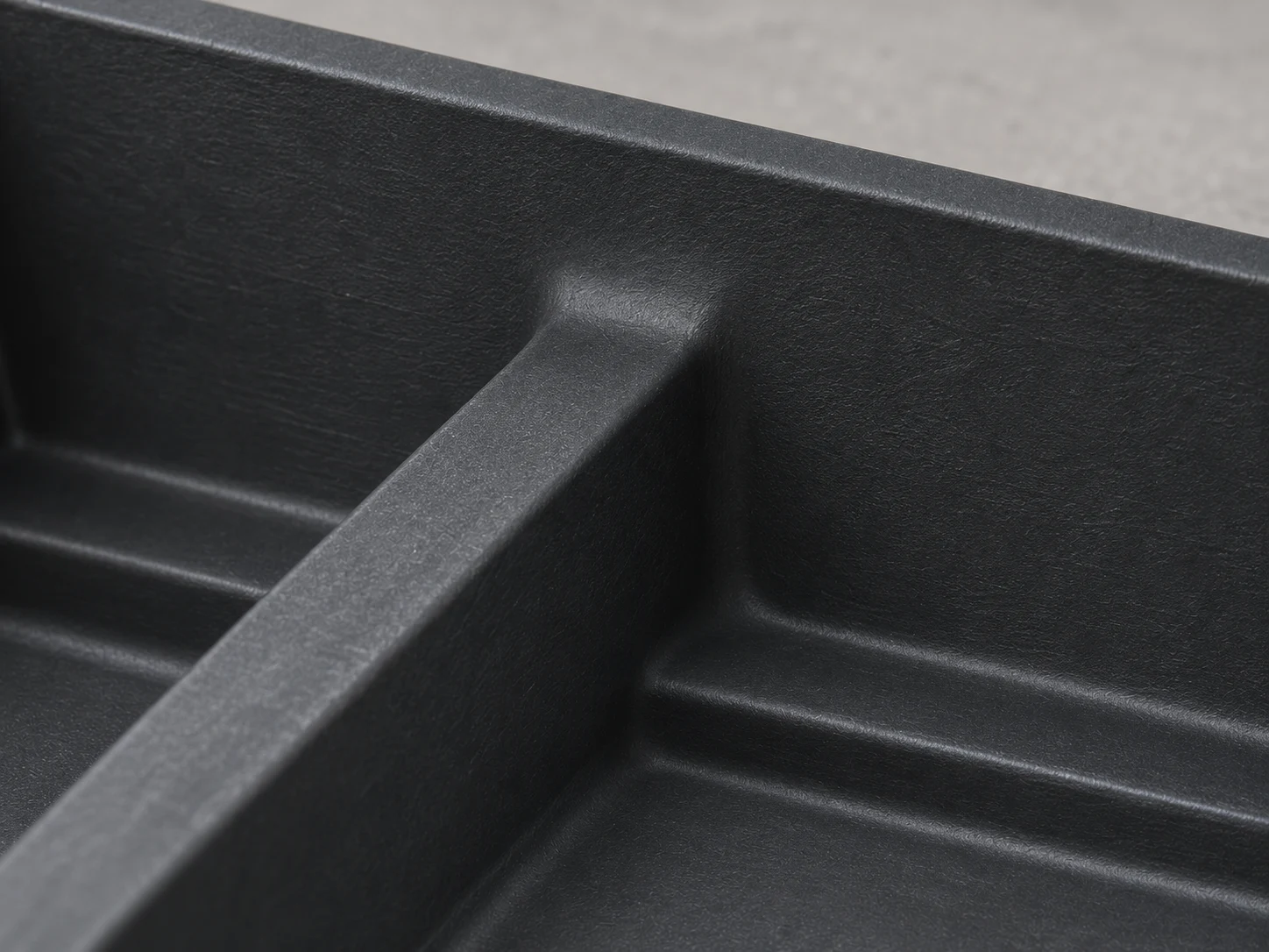
Define contact, cosmetic and assembly areas on the drawing. Agree on gate vestige, parting lines and measurable surface targets for the molded components, then check those areas on samples.
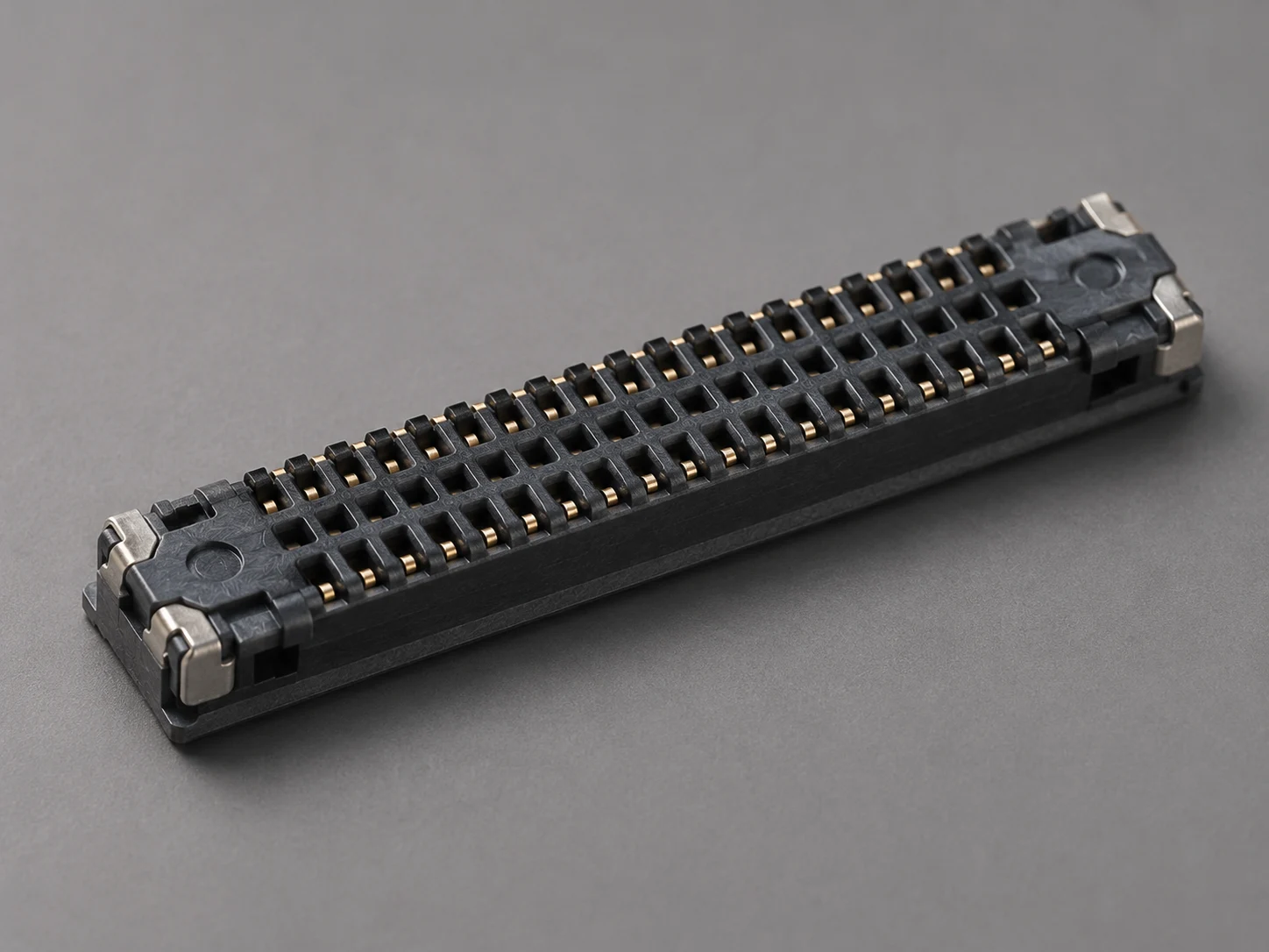
Select tool finish with fine cores, cavity depth and draft in mind. Check surface replication and release on samples of the selected LCP grade.
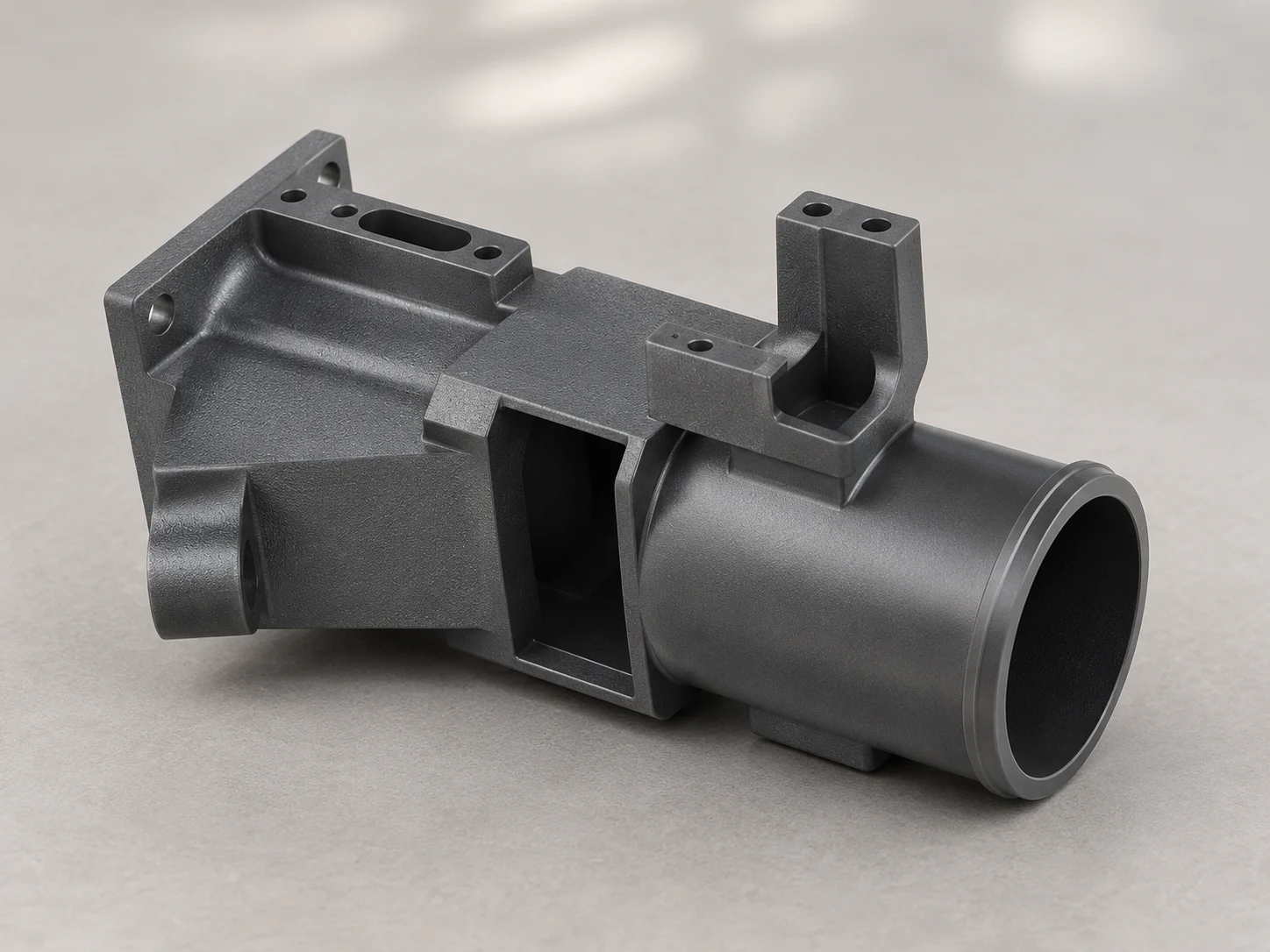
Define texture on non-contact surfaces and specify finish separately for mating, sealing and contact areas. Check draft, replication, roughness and any friction target on molded samples.
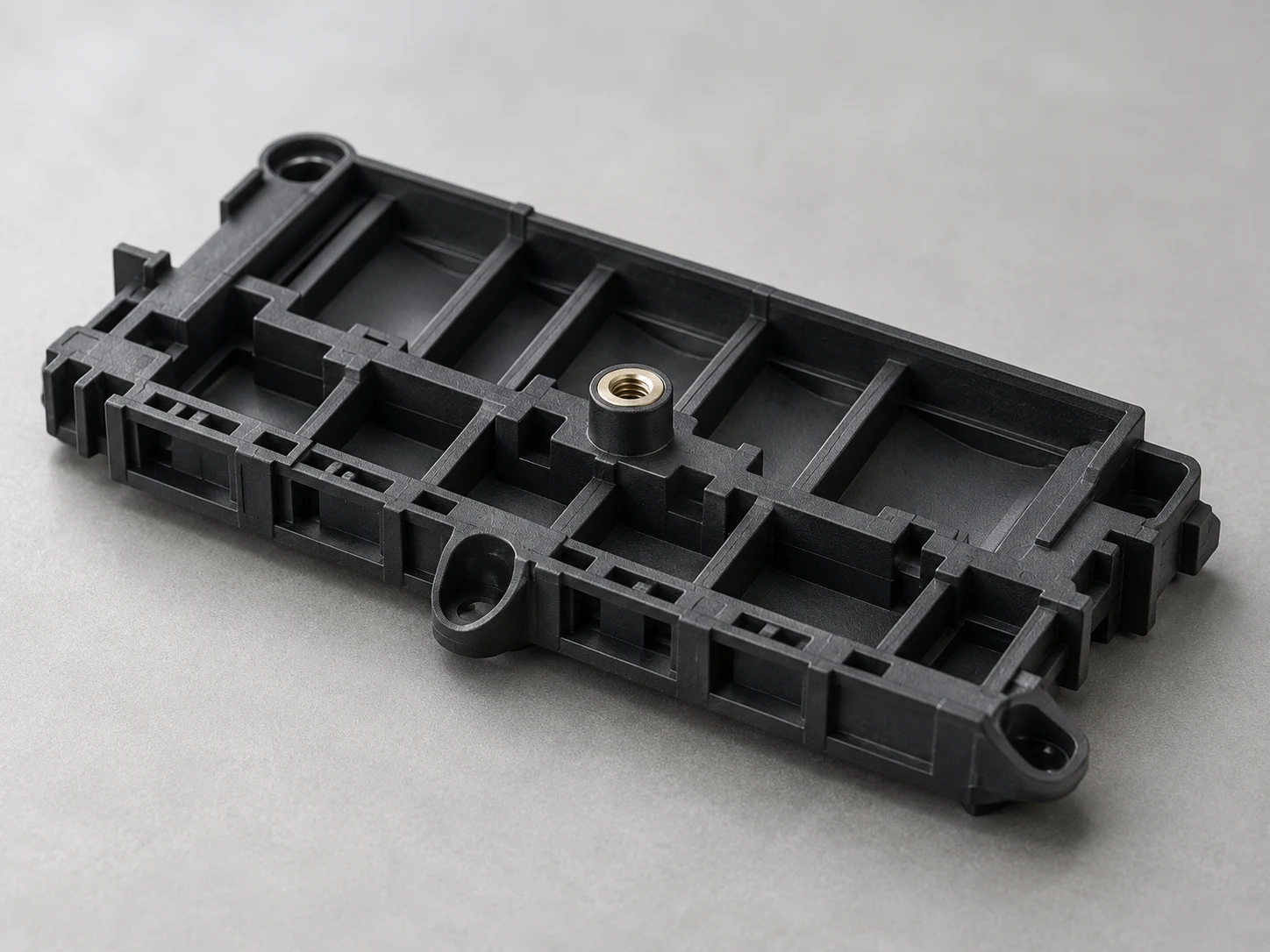
Establish datums for locating holes, terminal partitions and fastening faces, checking flash, warpage and assembly interference. Metal contacts and inserts are separate components; validate function on the actual assembly.
Record grade, drying and flow conditions. Inspect contact location, coplanarity and thin-wall fill, then validate reflow, insulation and mating cycles under the specified assembly conditions.
The table uses Celanese VECTRA E130i data from Material Data Center. E130i is an LCP grade with 30% glass reinforcement. Confirm the injection melt and mold temperature ranges with the supplier for the selected grade.
| Property | Reference value | Method / conditions |
|---|---|---|
| Density | 1610 kg/m³ | ISO 1183 |
| Tensile modulus | 16000 MPa | ISO 527 |
| Stress at break | 160 MPa | ISO 527 |
| Notched Charpy impact strength | 38 kJ/m² | ISO 179/1eA; +23°C |
| Melting temperature | 335°C | ISO 11357-1/-3; 10°C/min |
| Temperature of deflection under load | 270°C | ISO 75-1/-2; 1.80 MPa |
| Electric strength | 32 kV/mm | IEC 60243-1 |
| Item | Reference / guidance | Method / conditions |
|---|---|---|
| Linear thermal expansion: parallel | 7 × 10⁻⁶/K | ISO 11359-1/-2 |
| Linear thermal expansion: normal | 20 × 10⁻⁶/K | ISO 11359-1/-2 |
| Molding shrinkage: parallel | 0.1% | ISO 294-4, 2577 |
| Molding shrinkage: normal | 0.4% | ISO 294-4, 2577 |
| Humidity absorption | 0.03% | Sim. to ISO 62 |
| Predrying before molding: alternatives | 150°C / ≥6 h OR 170°C / ≥4 h | Desiccant dryer; producer guidance for Ei grades and V143XL, not two consecutive stages |
Use separate parallel and normal values. Choose one of the listed drying schedules. Melting temperature is 335°C, and HDT is 270°C at 1.80 MPa. Compare thermal-expansion and humidity results under matching test conditions and assess reflow and long-term service on the assembly.
Reference: Celanese VECTRA E130i data hosted by Material Data Center / Altair; actually read October 21, 2026. No revision date is shown in the captured page.
Connect LCP grade, flow paths and tooling with thin walls, contact location and assembly requirements in one review.
Translate critical dimensions, thermal history and electrical function into sample checks and validation plans linking development with production.
Use drawings and dimensional inspection support, including CMM, to focus on location, coplanarity and fit; confirm actual function through project testing.
Use ISO 9001 / ISO 13485 quality systems and material, sample and process records to support the transition from development to production.
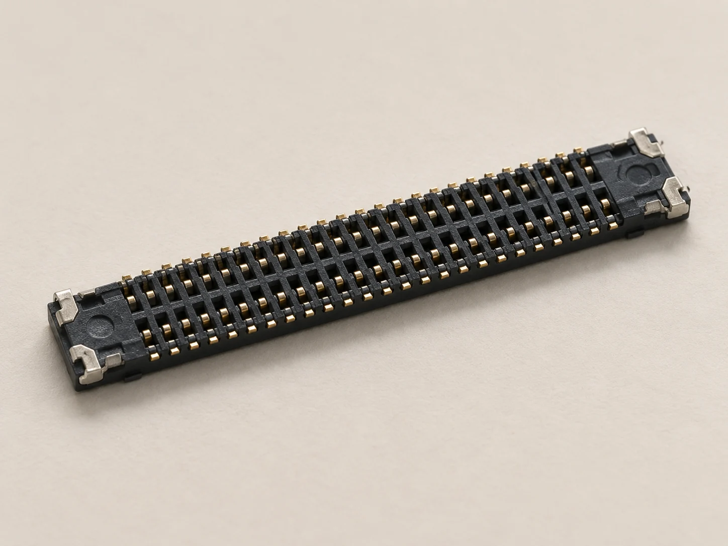
LCP stands for liquid crystal polymer. The material used for these molding projects is a thermotropic, melt-processable engineering plastic, often compounded with glass reinforcement. Its high flow and low thermal expansion make it a candidate for thin-wall connectors and small precision electrical structures.
Flow creates orientation in the polymer and reinforcement, so shrinkage, expansion and loading require directional assessment. High flow does not eliminate weld lines, warpage or drying requirements; establish suitability from the grade and flow path through actual assembly validation.
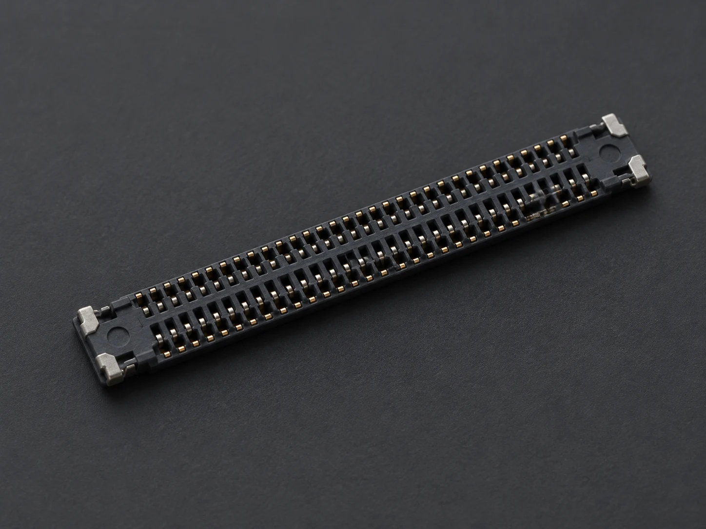
Fine partitions and contact arrays combine filling, terminal location and coplanarity requirements. Select the grade for actual mating dimensions and thermal exposure, then verify insulation and assembly function.
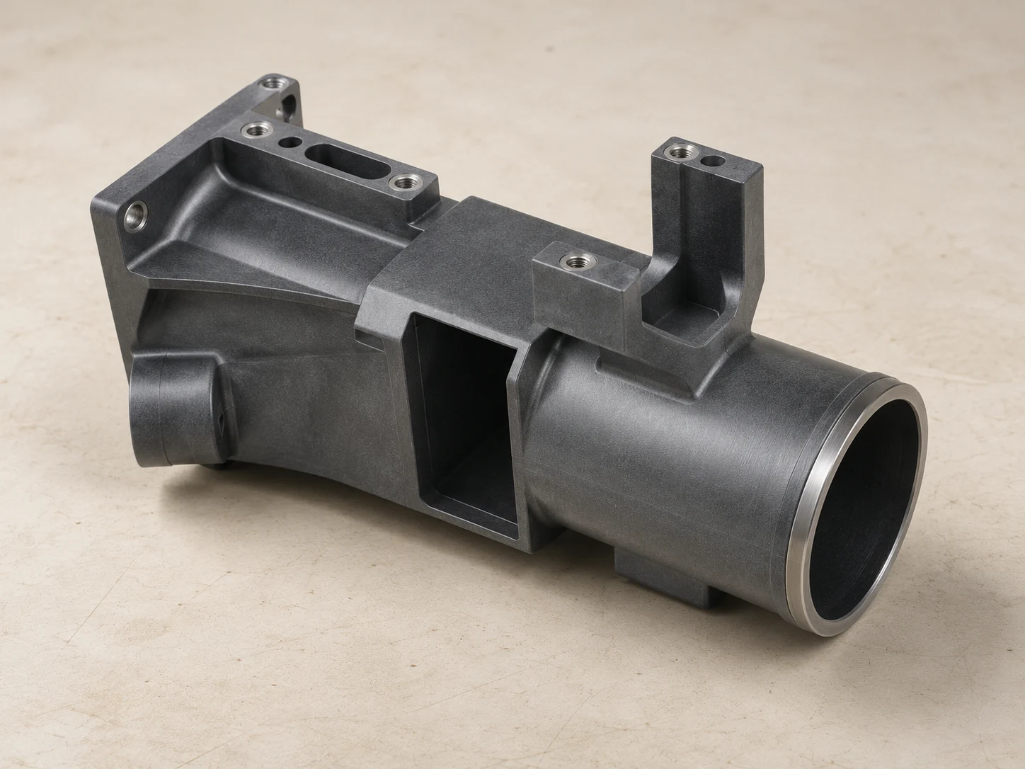
Review multiple ports, thin walls and ribs together for filling and interface dimensions. Establish location, loading and assembly requirements from the drawing, then validate function on actual samples.
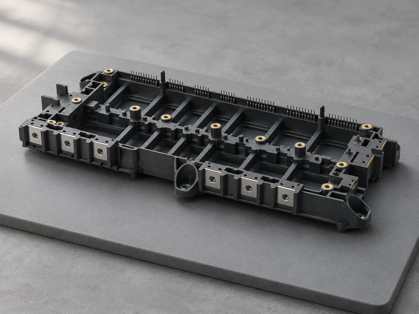
Review local heat sources, electrical spacing and metal interfaces in the inverter structure. Use the actual temperature, fastening loads and insulation requirements to select the grade and define the validation plan.
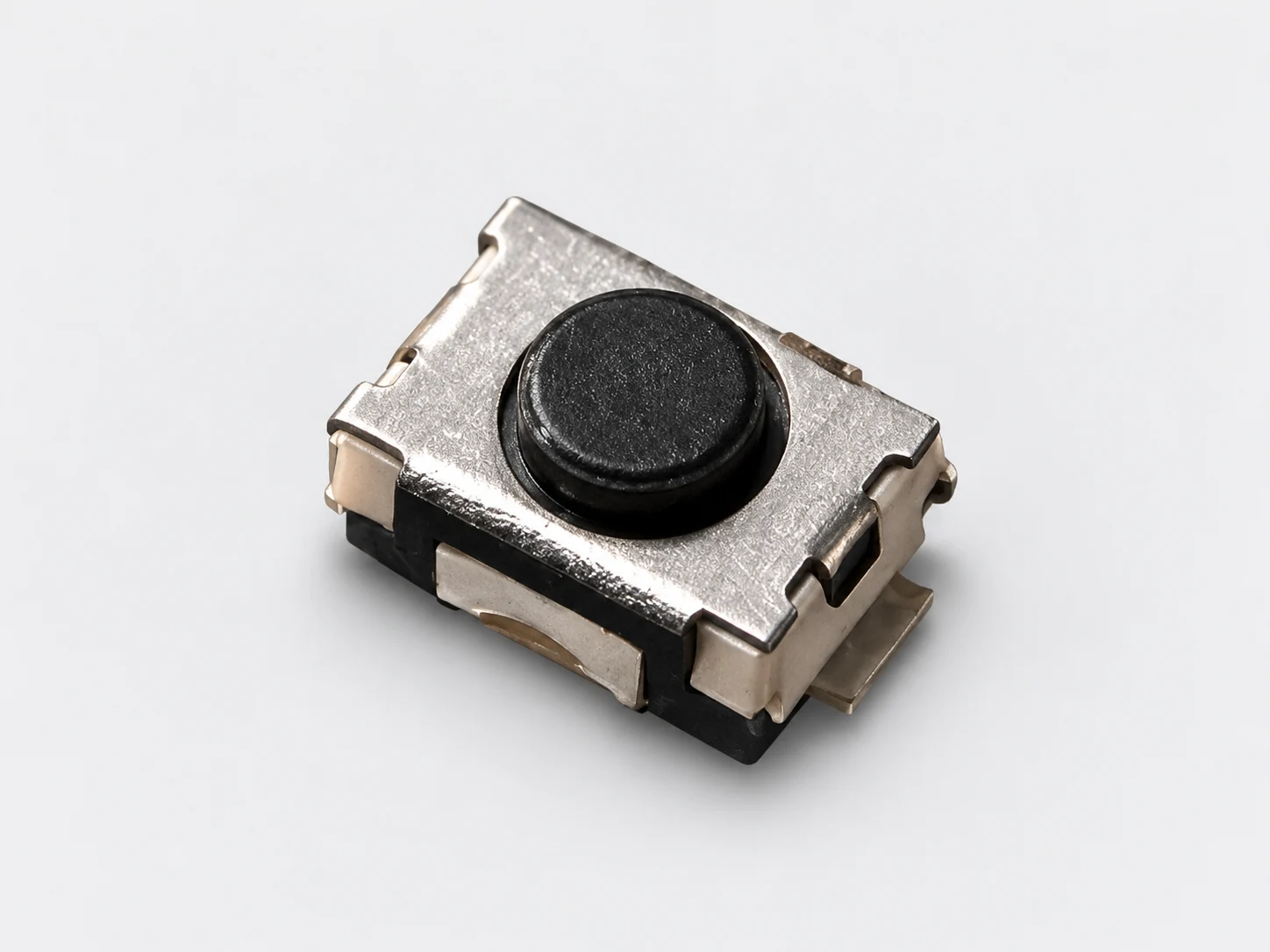
Polymer structures in switches help locate contacts and maintain assembly clearances. Check contact position, thermal cycling, repeated actuation and insulation on the complete assembly.
Consider LCP when fine partitions, contact location and thermal exposure jointly shape the design. Compare flow, directionality and assembly needs together rather than selecting by tensile strength alone.
Specialty resin, fine tooling and validation trials all affect project cost. Assess the route against quantity, geometry and function, retaining equivalent acceptance conditions when comparing alternative materials.
LCP INJECTION MOLDING FAQ
Common questions about thin walls, directionality, drying and application validation.
This page concerns thermotropic, melt-processable LCP molding grades such as glass-reinforced VECTRA E130i. Liquid crystal polymer is a broad term; do not transfer processes or properties from other liquid-crystalline materials, fibers or films directly to molded parts.
Relevant grades combine high flow, stiffness and low thermal expansion. The producer also describes shear-thinning behavior, so filling conditions influence flow. Achievable walls and contact spacing still depend on grade, flow length, tooling and validation rather than a universal minimum.
The E130i sheet lists two alternative desiccant-dryer schedules for Ei grades and V143XL: at least 6 hours at 150°C or at least 4 hours at 170°C. Use the selected grade’s schedule and confirm its moisture limit with the supplier.
Shrinkage and thermal expansion differ by direction; low parallel shrinkage does not ensure uniform behavior. The E130i reference lists 0.1% parallel and 0.4% normal shrinkage. Review gates, fine-wall flow paths and cooling against contact location and coplanarity, then check actual samples.
No. Where flow fronts meet around holes, terminals or divided paths, local strength can limit the design. Review weld-line location against mating, clip and fastening loads, then verify through tooling decisions, molding trials and functional tests.
The E130i melting result is 335°C at 10°C/min, and its HDT is 270°C at 1.80 MPa. Obtain the supplier’s melt and mold settings for the selected grade. Assess solder reflow and long-term loaded service separately on the assembly.
Specify the rating, test, grade, color and thickness needed for the intended use. For medical contact, document contact conditions, sterilization and material requirements, then validate the finished device.
Share drawings, quantity and thin-wall, thermal and critical-assembly requirements. Our team will review the material and tooling route and prepare a quote.
Get an LCP Molding Quote