

01
Prototype & Bridge Production
Evaluate clear-part appearance, assembly and material behavior with molded samples. Plan tooling around design maturity, validation goals and subsequent demand.
Built for production.
Take your design from tooling to repeat production of custom plastic parts.
Manufacturing Capabilities
Plastic Injection MoldingCustom plastic parts for production Tooling & Design SupportPrepare your part design for tooling High-Volume ProductionPlan repeat runs around your delivery needsMaterials & Finishes
Made for smaller runs.
Produce resin parts with silicone molds for design validation and small batches.
Small-Batch Capabilities
Vacuum CastingResin parts made with silicone moldsLow-Volume ProductionFrom trial parts to small-batch deliveryAppearance & Fit ChecksPrepare multiple parts for product checksMaterials & Finishes
Other Services
Machining, printing, and supporting services for specific part needs.
Materials & Finishes
Explore material performance and appearance options separately.
Explore Materials & Finishes
Injection Molding Materials
Choose molding materials for strength, heat resistance and appearance.
Manufacturing Knowledge
Find articles, answers, and case studies to help prepare your project.
Start with your part requirements.
Contact PlasticHubs for help with quotes, files, delivery, and orders.
Files, Orders & Delivery
Industries
Explore manufacturing options for your product application.
Start with your manufacturing needs
From tooling to production of plastic parts.
Small batches of resin parts made with silicone molds.
Start with your design, material, and quantity.
Bring clear-part appearance and assembly requirements into one molding plan. Select an acrylic grade for lighting covers, light guides and instrument covers, with optical surfaces, critical dimensions and sample criteria defined before production.
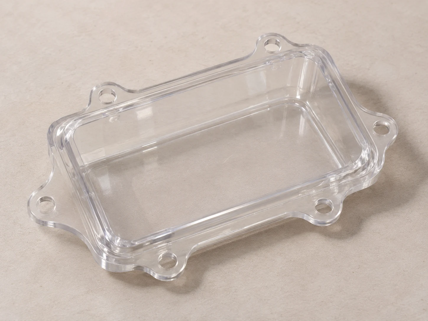
Tell us how the part will be used and which surfaces must remain clear. Cleaning-agent exposure, outdoor conditions and mounting details also affect material and tooling decisions.
Discuss your project ↗Evaluate clear-part appearance, assembly and material behavior with molded samples. Plan tooling around design maturity, validation goals and subsequent demand.

Bring cavities, tooling, color and cosmetic acceptance into the production plan. Use approved samples to connect tool trials, dimensional review and subsequent batch requirements.

Review clear, tinted and surface requirements together. Specify light transmission, color and the visible areas to check on molded samples of the selected grade.
Start with your drawings, quantity and clear-part requirements.
| Item | Project review |
|---|---|
| Material & color | Select the grade for optical, thermal and service requirements |
| Tooling & cavities | Review geometry, demand and visible surfaces |
| Critical dimensions | Agree on datums, tolerances and measurement methods |
| Sampling & production | Approve trial samples and cosmetic and functional criteria |
| Surfaces & secondary operations | Distinguish molded surfaces, coatings and printing; review compatibility |
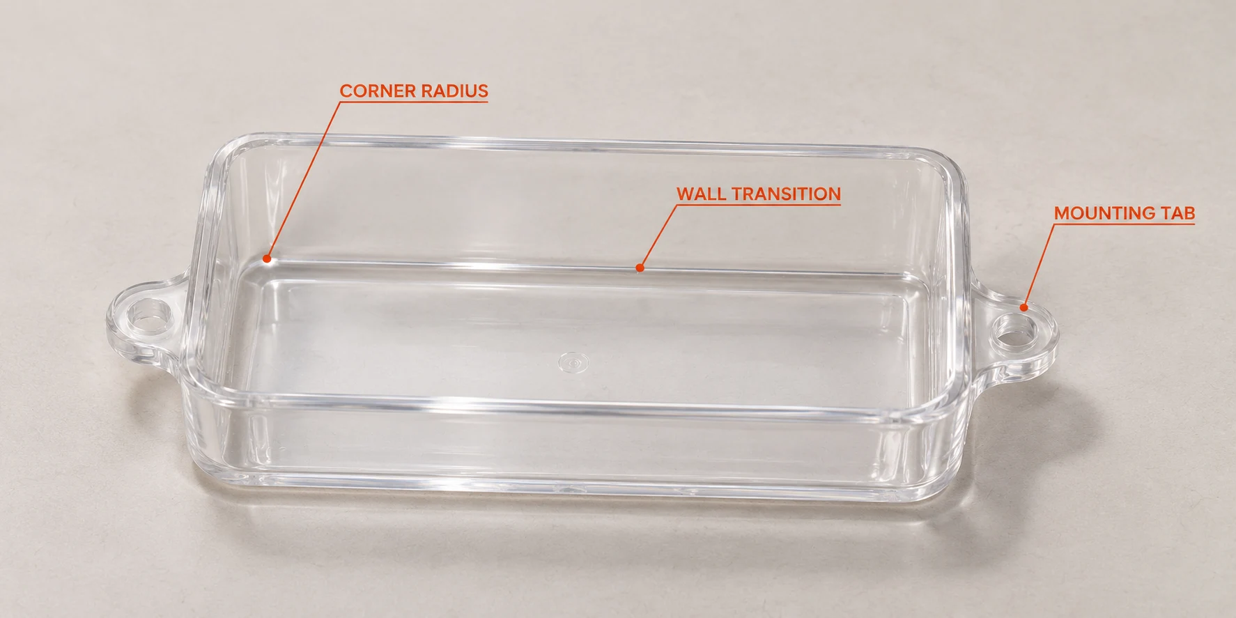
Review thickness changes and local material buildup for filling, sink and cooling. Internal defects can also affect the appearance of clear parts.
Coordinate gate location, venting and flow paths with visible-surface requirements. Discuss weld lines and gate vestiges during tool review.
Review geometry, mold finish, draft and ejection locations for cracking risk. Consider local features together with the material choice.
Identify critical optical areas, review mold surfaces, contamination and handling scratches, and agree on viewing and inspection conditions.
Separate molded surfaces from secondary coatings and printing, then confirm the suitable option for the part.
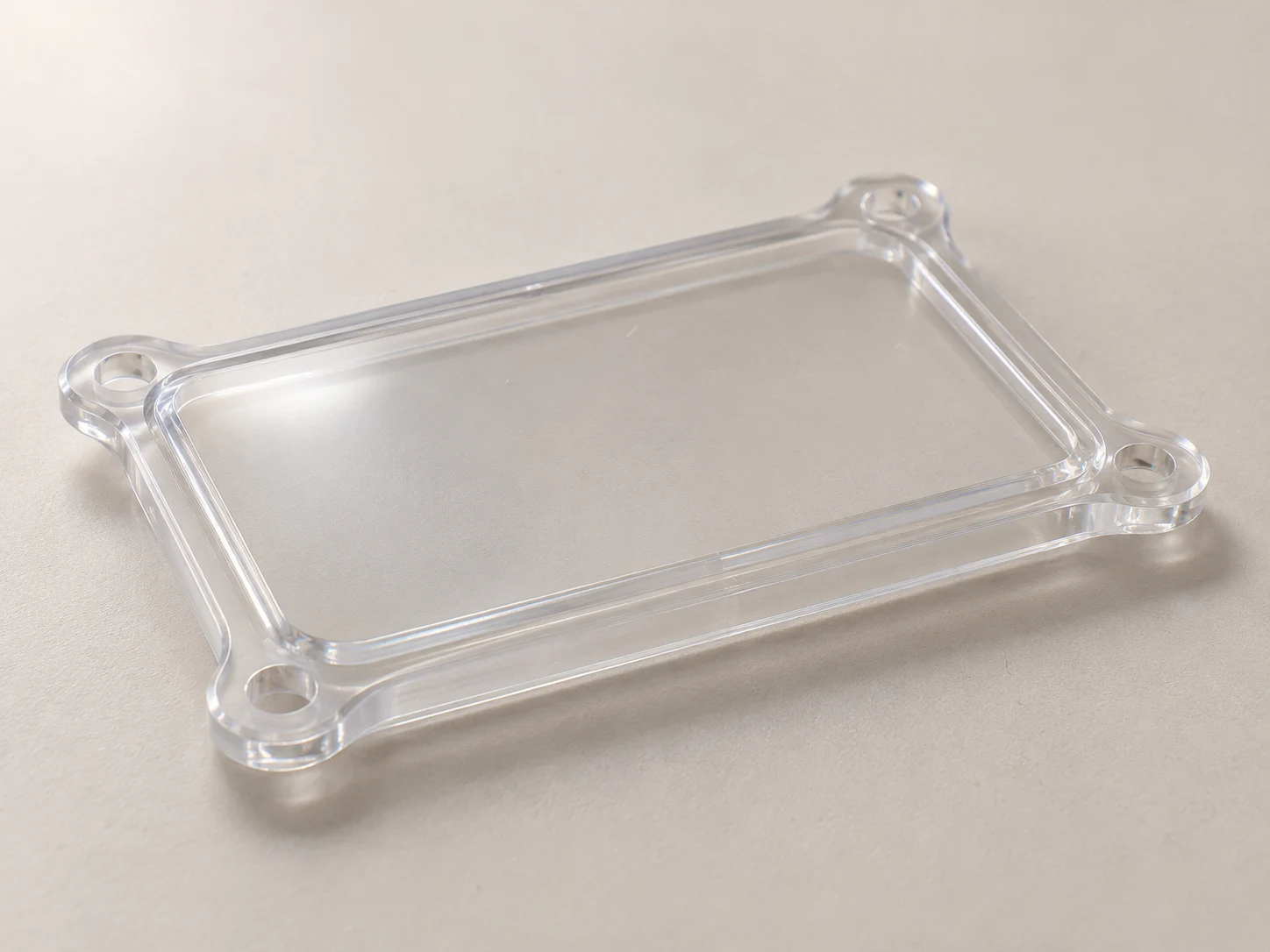
Replicate a smooth tool surface. Final clarity and gloss depend on the grade, mold and processing conditions.
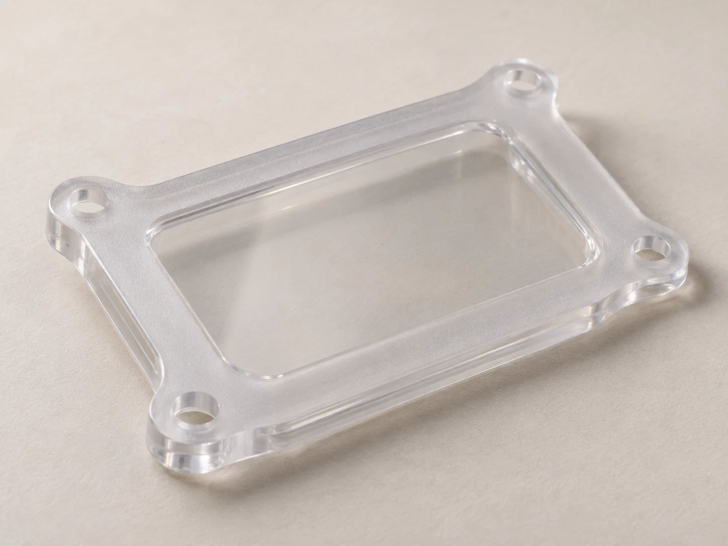
Use tool texture to change the appearance of selected areas. Texture affects light transmission and scattering, so confirm the intended effect with samples.
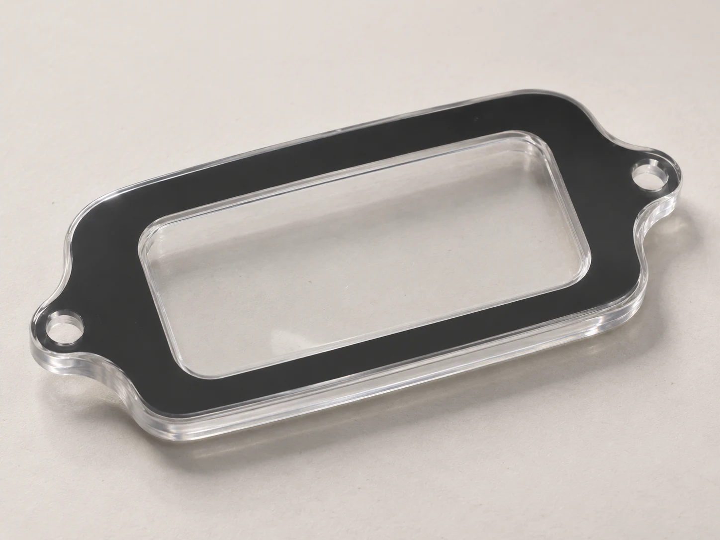
Evaluate color coverage on areas that do not need to transmit light. Confirm coating compatibility, adhesion and service conditions before selecting the process.
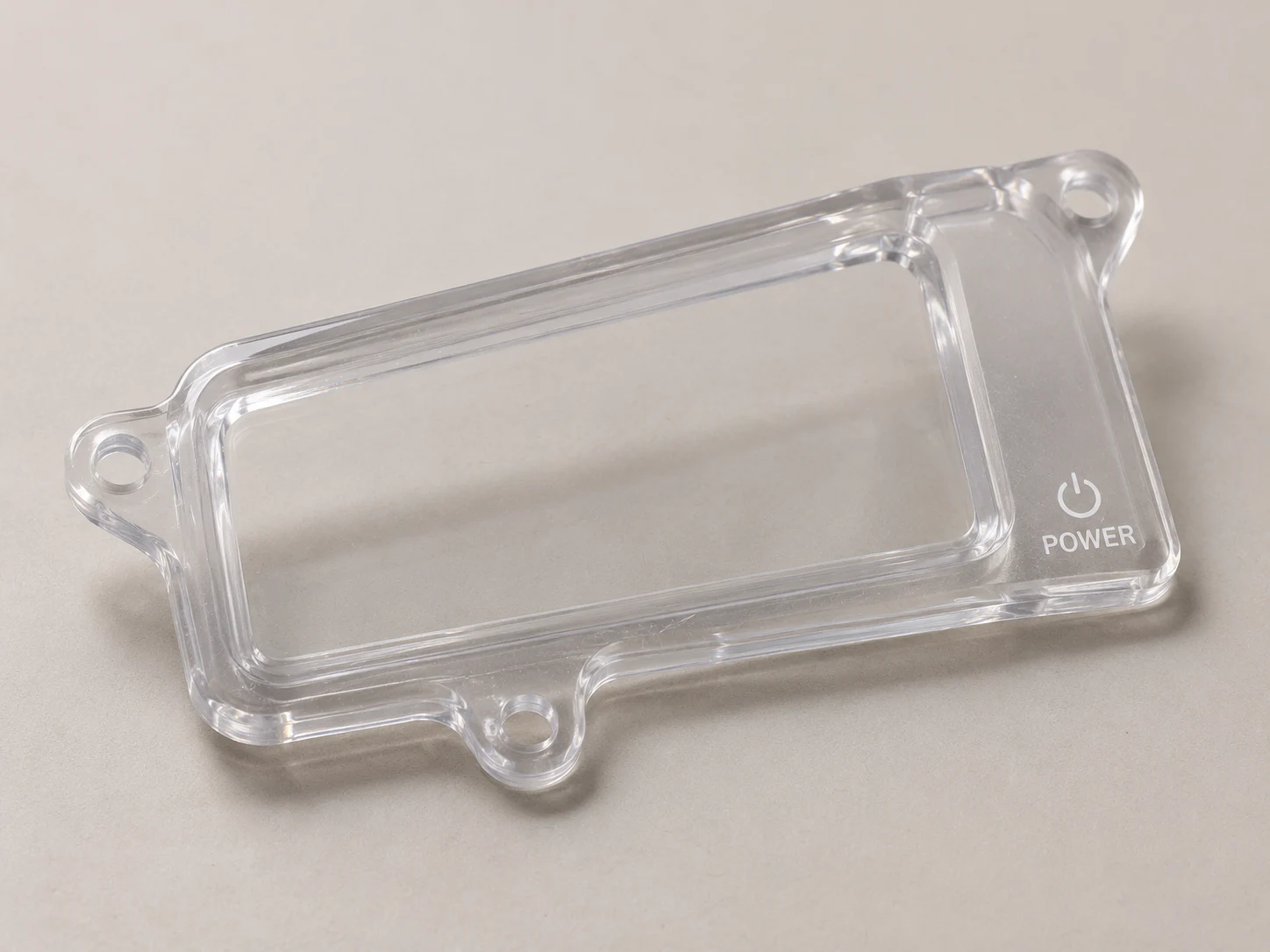
Review ink, adhesion and cleaning-agent requirements for logos, symbols and local markings. Keep artwork clear of critical optical areas.
Define separate acceptance criteria for critical dimensions, black specks and bubbles in visible zones, weld lines and scratches. For transmission or other optical targets, agree on the test method, conditions and samples.
The table pairs typical properties with Röhm’s processing recommendations for PLEXIGLAS 8N. Use the exact grade and color when comparing optical, mechanical and thermal data.
| Property | Typical value | Method / conditions |
|---|---|---|
| Luminous transmittance | 92% | ISO 13468-2; D65; 3 mm |
| Tensile modulus | 3,300 MPa | ISO 527; 1 mm/min |
| Stress at break | 77 MPa | ISO 527; 5 mm/min |
| Strain at break | 5.5% | ISO 527; 5 mm/min |
| Density | 1.19 g/cm³ | ISO 1183 |
| Property | Typical value | Method / conditions |
|---|---|---|
| Vicat softening temperature | 108°C | ISO 306; B/50 |
| Deflection temperature under load | 98°C | ISO 75; 1.8 MPa |
| Melt temperature | 220–260°C | PLEXIGLAS 8N injection melt range |
| Mold temperature | 60–90°C | PLEXIGLAS 8N injection mold range |
| Predrying | ≤98°C; 2–3 h | Maximum temperature; desiccant drier |
HDT and Vicat describe different heat tests. The melt temperature applies to injection processing. Set drying for the selected grade and storage conditions, and review the intended service temperature and optical targets with your drawing.
Reference grade: Röhm PLEXIGLAS 8N, product information dated 2020-02-20.
Bring grade choice, visible surfaces and geometry into one review to identify clear-part molding risks early.
Connect tooling, trial samples and production needs through our group manufacturing resources, reducing gaps between project stages.
Define sample acceptance around color, clear areas, assembly dimensions and the service environment.
Turn drawing and appearance requirements into clear review points throughout quotation, sampling and production discussions.

Here, acrylic means polymethyl methacrylate (PMMA), an amorphous thermoplastic. Injection molding uses molding-grade pellets to create parts with defined geometry and function.
Select a PMMA injection-molding grade for flow, heat, impact and optical targets. Use the molding-grade datasheet when comparing it with sheet-grade PMMA.

Review transmission, appearance and thermal conditions for lighting covers, with visible surfaces and mounting details defined.
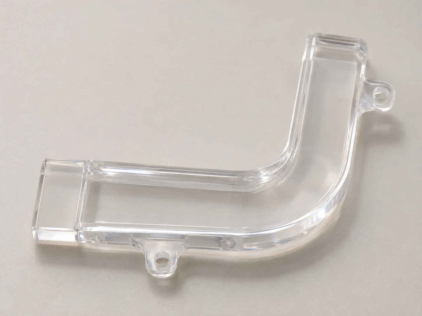
Components that carry light to selected areas, with geometry, tool surfaces and optical behavior validated through samples.
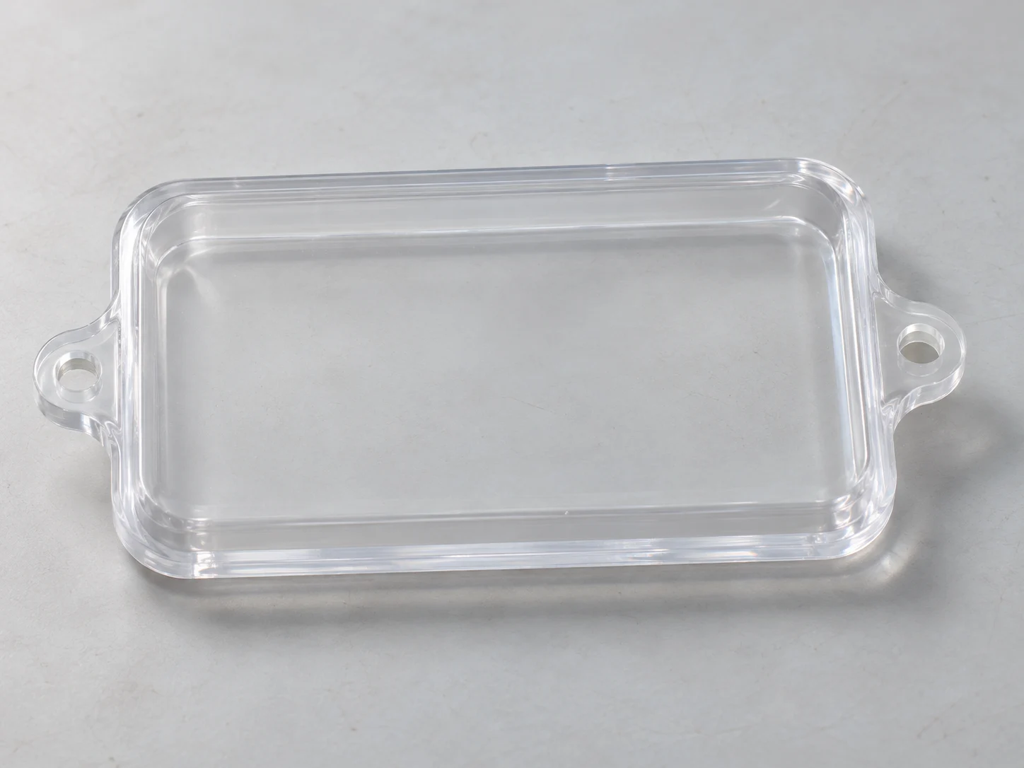
Clear windows for displays and instruments, considering the viewing area, mounting features and cleaning exposure.

Specify the optical target, locating features and acceptable surface defects for the light path. Review gate placement and verify the result on molded samples.
An appropriate PMMA grade can serve parts requiring clear appearance and weathering performance. Molding integrates the shape, mounting areas and local features into one component; economics still depend on tooling investment, geometry and order volume.
Compare PMMA and PC grades for impact, temperature, sustained stress and exposure to cleaning agents. Use matched test conditions and approved samples for the visible and loaded areas.
ACRYLIC INJECTION MOLDING FAQ
Material selection, clear-part appearance, and the information needed to start your acrylic molding project.
Yes. Injection-molding grades of PMMA are used for lighting covers, light guides and other optical or technical parts. Specify the grade and the optical and mechanical requirements in your drawing.
Start with optical, thermal, impact, color and service requirements, then compare grades against wall thickness and flow paths. Supplier typical data supports screening; use suitable samples and tests to confirm performance.
Temperatures depend on the grade and part. For the PLEXIGLAS 8N example on this page, the supplier lists a melt range of 220–260°C and an injection mold range of 60–90°C. These are grade-specific references, not universal settings for acrylic.
Review resin condition, contamination, feeding, gates, venting, filling and holding. Use tool-trial samples to distinguish moisture-related bubbles from flow marks, contamination and other causes.
Compare the selected grades under the same service conditions, including transmission, impact, operating temperature, sustained stress and cleaning-agent exposure. Provide target values and test conditions for critical requirements when requesting a quote.
Key factors include tooling and cavities, part size and geometry, selected material, quantity and cosmetic acceptance requirements. Clear visible surfaces affect tooling and inspection planning. Drawings and quantities are needed for a project quote.
Provide CAD, drawings, quantities and material or performance requirements, identifying visible surfaces, critical dimensions and mounting conditions. During sample review, confirm dimensions, assembly, appearance and agreed optical requirements separately.
Share your CAD, material, quantity, and key requirements. Our team will review your project and prepare a quote.
Request a Quote