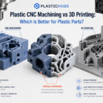
A prototype can match the CAD model and still fail during assembly, sealing, wear, or environmental testing. That failure often starts with a poor choice between plastic CNC machining and 3D printing. The fastest process may not reproduce the material, features, or surface conditions that the test needs.
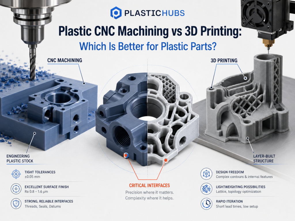
Choose 3D printing when the immediate question is about shape, space, ergonomics, or geometry that cutting tools cannot reach. Choose plastic CNC machining when the test depends on a specified engineering-plastic grade, controlled holes or mating surfaces, machined threads, or repeatable low-volume parts. If the part needs both complex internal geometry and precisely finished interfaces, use the processes in sequence.
Choose the Process by What the Part Must Prove
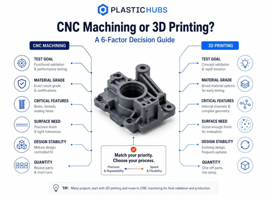
Start with what the prototype or production part must prove. Do not rely on a broad claim that one process is always faster, cheaper, or more accurate. The table gives the first direction, while the later sections explain when that choice can change.
| Part requirement | Evaluate plastic CNC machining first | Evaluate 3D printing first |
| Test objective | Assembly, load, wear, friction, heat, chemical exposure, sealing, or repeated use | Appearance, space claim, ergonomics, design review, or early concept screening |
| Material requirement | A specified stock grade is part of the test | A printable filament, resin, or powder meets the test requirement |
| Function-controlling features | Bores, slots, threads, flat datums, sealing faces, sliding surfaces, and controlled fits | Enclosed channels, lattices, hollow forms, organic surfaces, and integrated features |
| Surface requirement | A machined surface or a controlled finishing allowance is required | Process texture is acceptable or the planned finish can be applied consistently |
| Design status | The design is stable enough to justify programming, workholding, and inspection | The design is still changing and several versions must be compared |
| Quantity | Repeat prototypes or low-volume parts allow setup to be shared across the batch | One or a few parts are needed with limited setup |
| Main project risk | The sample may not fit, seal, carry load, or represent the specified plastic | CNC may consume time and cost before the geometry is settled |
Choose plastic CNC machining when function depends on the material and interfaces
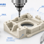
Start with plastic CNC machining when the part needs a specified engineering-plastic stock grade. It is also a good choice when the part must be checked against a drawing. Examples include a bearing bore, gasket face, thread, sliding guide, locating datum, or housing interface.
These are function-controlling features. They are dimensions or surfaces that can cause a fit, motion, sealing, fastening, or inspection failure. Marking them on the drawing helps the supplier plan machining, workholding, and inspection around the real risk.
CNC also suits repeat low-volume parts when the design is stable and the same setup can serve the full batch. But CNC is not automatically the best choice for every functional prototype. A hard-to-reach internal channel or a design that changes daily can make machining an expensive early step.
Choose 3D printing when geometry and iteration drive the decision
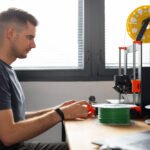
Start with 3D printing when the team needs to compare several designs, check an enclosure envelope, or review ergonomics. It also suits geometry that cutting tools cannot reach. Examples include enclosed flow paths, integrated ducts, lattices, hollow forms, and organic shapes.
The exact printing route matters. FDM/FFF requires checks for layer bonding, warpage, and support removal. FDM/FFF requires checks for layer bonding, warpage, and support removal. SLA/DLP requires review of washing, support removal, post-curing, and dimensional change. SLS/MJF requires review of depowdering, thermal history, surface texture, and dimensional compensation.
A layer-height or XY-resolution value does not by itself predict the accepted part. The supplier must evaluate the complete process, including orientation and post-processing, against the features the part must prove.
Use both when the geometry and the interfaces favor different processes
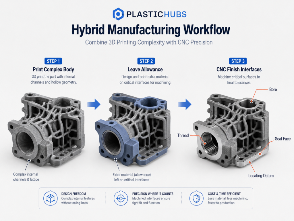
A hybrid route can resolve a false either-or decision. The main body may be printed to create an enclosed channel or integrated shape. Extra material can be left on a bore, thread, sealing face, or locating surface for CNC finishing.
The processes can also be used at different development stages. Print the part while its form is changing. Machine the selected design for material and assembly tests, then move to molding when the design and quantity justify tooling.
How Plastic CNC Machining and 3D Printing Produce Different Results
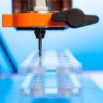
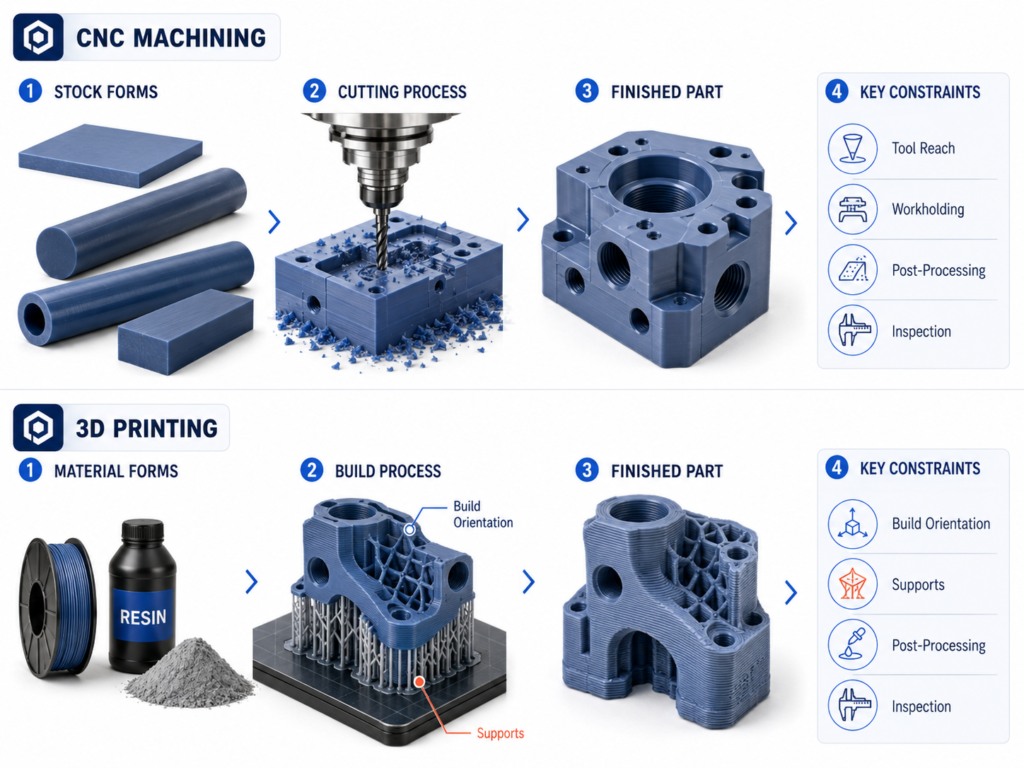
Plastic CNC machining removes material from plate, rod, tube, or block stock. 3D printing builds the part from filament, liquid resin, or powder. One route depends on cutter access and workholding; the other depends on the build process.
| Comparison | Plastic CNC machining | 3D printing |
| Process logic | Material is removed from solid stock | Material is deposited, cured, or fused layer by layer |
| Primary geometric constraint | Cutter diameter, tool reach, setup direction, and clamping access | Build orientation, supports, drainage, depowdering, and build envelope |
| Material form | Commercial sheet, rod, tube, or block in an available grade | A process-compatible filament, resin, or powder system |
| Typical process evidence | Toolpath, setup, stock condition, and dimensional inspection | Build orientation, machine/material system, post-processing, and dimensional inspection |
| Common defect or failure risk | Distortion from clamping or heat, inaccessible features, burrs, and stock stress | Warpage, support damage, trapped material, cure change, and direction-dependent behavior |
The same CAD file may be easy to print but hard to machine. The reverse can also be true. Each route needs its own DFM review before the team compares price and lead time.
Engineering-Plastic Requirements and Test Validity
Engineering-plastic requirements are often the main reason to select plastic CNC machining instead of 3D printing. When a required grade is available as stock, machining can produce a sample from that grade without replacing it with a printable material system.
That advantage has a limit. A machined sample reflects the selected stock material and its machining history. It does not reproduce molding effects such as flow direction, weld lines, gate effects, shrinkage, or molding stress.
The same material-family name also does not establish equivalence. Printed PA12, machined PA6/6, and injection-molded glass-filled nylon may all be called nylon, yet they differ in resin, filler, moisture condition, manufacturing history, and direction-dependent properties.
| Test question | What CNC stock can show | What a printed polymer system can show | What still requires review |
| Assembly fit | Fit with machined holes, datums, and interfaces | Fit of the printed geometry in its as-built or finished state | Process capability and inspection method |
| Load or stiffness | Behavior of the specified stock grade under the sample conditions | Behavior of the selected print material and build orientation | Whether either route represents the final production material |
| Wear and friction | Contact behavior of the stock grade and machined surface | Contact behavior of the print material and finished texture | Counterface, lubrication, temperature, and test duration |
| Heat or chemicals | Response of the selected stock grade | Response of the selected printable system | Exact exposure, stress, time, and material condition |
| Pre-molding validation | Geometry, inserts, fasteners, interfaces, and some material behavior | Form, access, assembly sequence, and selected functional checks | Molded-part effects and final production validation |
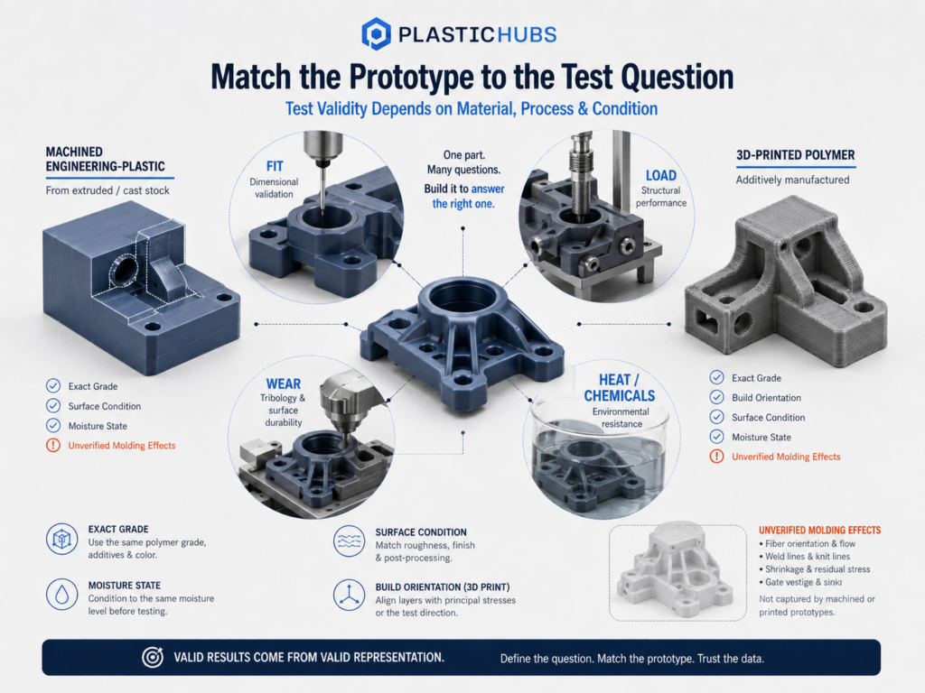
Before using a prototype as material evidence, compare the exact grade, filler, moisture state, heat treatment, and data-sheet test conditions. If the project cannot match them, state what the prototype can prove. Also state what remains unverified.
Dimensional Control, Fit, and Surface Requirements
Plastic CNC machining usually gives more direct control over holes, flat faces, slots, threads, and mating surfaces. But that does not guarantee one tolerance for every part. Material grade, wall thickness, stock stress, workholding, heat, toolpath, and inspection still affect the result.
3D-printed parts can meet many assembly requirements, but the supplier must name the process and finished condition. FDM/FFF is sensitive to orientation and warpage. SLA/DLP and SLS/MJF have different risks from curing, powder removal, texture, and size adjustment.
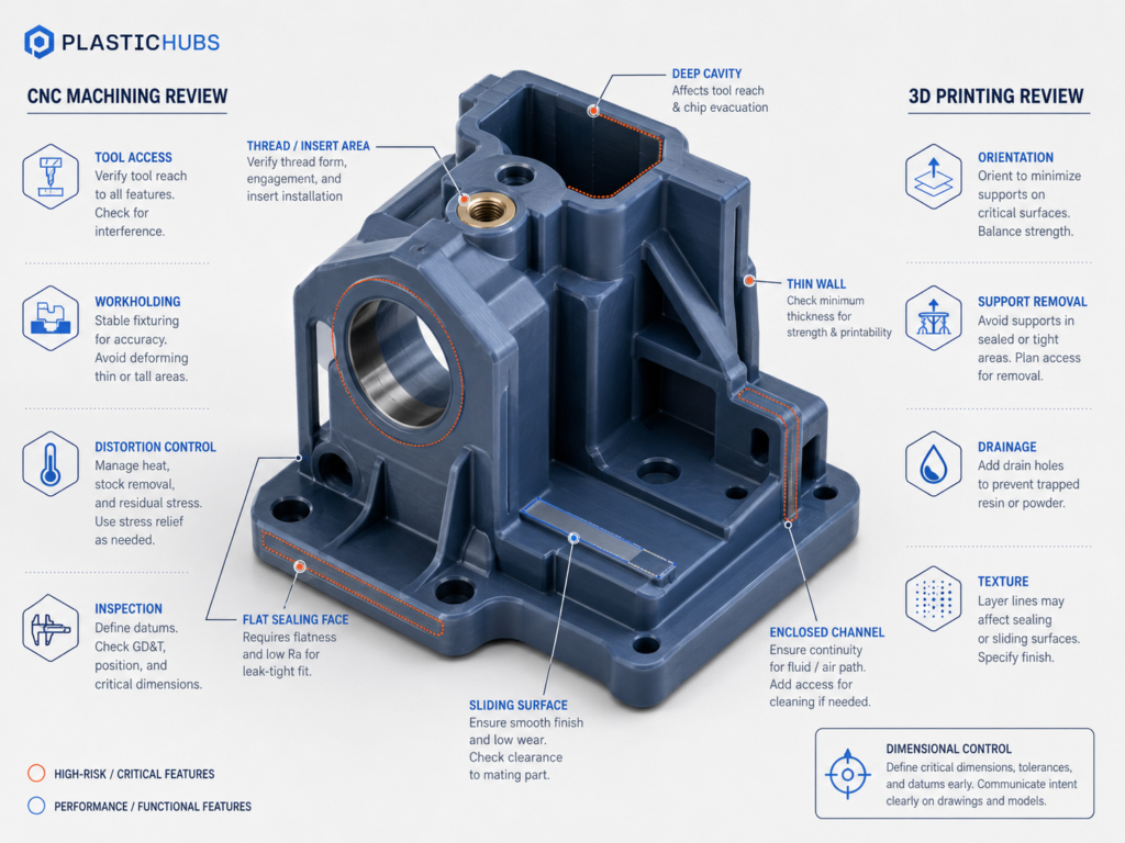
| Acceptance requirement | CNC review point | 3D-printing review point |
| Bore, pin, or controlled fit | Datum strategy, tool choice, workholding, and inspection | Orientation, feature compensation, and possible post-machining |
| Flat or sealing face | Stock stability, distortion control, toolpath, and finish | Warpage, support placement, surface texture, and finishing access |
| Thread or insert | Machined thread form, engagement, insert method, and inspection | Printed feature limits, insert installation, load, and cycle count |
| Sliding or bearing surface | Surface condition, burr control, material pair, and lubrication | Build texture, finishing consistency, orientation, and wear behavior |
| Repeat batch | Stock batch, program, fixture, tool condition, and sampling plan | Machine condition, build layout, material condition, and post-processing control |
The drawing should identify the datums and the dimensions or surfaces that control function. Noncontrolling dimensions should use practical tolerances so that cost and inspection effort remain focused on the features that can reject the part.
Surface requirements need the same care. “Smooth” is not an acceptance specification. State whether the surface must seal, slide, remain transparent, match a cosmetic sample, or receive another finish, then agree on the inspection method.
Geometry and DFM: Tool Access vs Build Feasibility
CNC and 3D printing fail for different geometric reasons. DFM should identify the features likely to cause rework, scrap, delay, or inspection failure before the quote is treated as comparable.
| Design feature | CNC DFM question | 3D-printing DFM question |
| Sharp internal corner | What cutter radius can reach the depth without excessive deflection? | Can the process reproduce and clean the corner at the selected orientation? |
| Deep narrow cavity | Is tool reach practical, and can chips and heat be controlled? | Can the feature build without trapped resin, powder, or support material? |
| Thin wall | Can it be clamped and cut without distortion? | Can it be built, cooled or cured, and handled without warpage? |
| Enclosed channel | Can it be drilled, split, or reached from another setup? | Are drainage and depowdering paths adequate? |
| Undercut or side feature | Does it require another setup, special tooling, or part separation? | Does orientation or support removal create damage or inaccessible surfaces? |
| Complex freeform surface | How many axes, setups, and finishing passes are needed? | Which orientation balances surface quality, dimensional change, and build stability? |
A process-neutral CAD model is not ready for either process. CNC may need larger internal radii, clamp access, shallower cavities, or split construction. Printing may need drainage, escape holes, support access, a new orientation, or machining allowance.
When you request both quotations, ask each supplier to state its DFM changes. A low price based on an unreviewed file is not equal to a quote that includes setup, print preparation, finishing, and inspection.
Cost, Lead Time, and Quantity: Compare Accepted Parts
There is no universal quantity at which CNC becomes cheaper than 3D printing. Geometry, part size, stock availability, print process, finishing, inspection, failure risk, and batch layout can move the crossover in either direction.
| Cost or schedule driver | Plastic CNC machining | 3D printing |
| Initial preparation | CAM, tool selection, workholding, setup, and first-part inspection | File preparation, orientation, supports, nesting, and process setup |
| Material | Stock grade, stock size, availability, and removed material | Filament, resin, or powder, support material, and build utilization |
| Geometry | Extra setups, long tool reach, undercuts, and finishing passes add time | Geometric complexity may add little build preparation, but supports and cleaning can add labor |
| Acceptance features | Machining and inspection are planned into the route | Compensation, reprinting, inserts, or post-machining may be required |
| Quantity | Setup can be distributed across repeat parts | Setup is often lighter, but machine time and post-processing remain for each build |
| Design change | CAM and fixture work may need revision | A revised file may be prepared and rebuilt with less fixed setup |
Compare total accepted-part cost, not only the first unit price. Include material changes, finishing, inspection, failed builds, scrap, and rework. Also include the cost of repeating a test when the first sample cannot answer the intended question.
Lead time needs the same type of review. A printed part may start sooner, while a machined batch may move faster after setup. Material supply, queue time, inspection, and design changes can matter more than the process name.
Where Each Process Fits in Product Development
An efficient development sequence changes the process when the engineering question changes. Early in the project, printed parts can eliminate weak concepts before the team pays for detailed machining and inspection.
Once the design is stable, a machined sample in the specified stock grade can support assembly and functional tests. If some geometry still favors 3D printing, print the body with extra material at the interfaces. Then finish those interfaces by CNC.
CNC machining can reduce risk before injection-mold tooling, but it cannot copy the full molding process. Use molded production parts for final checks when performance depends on flow, gate location, weld lines, shrinkage, texture, or molding stress.
RFQ Information That Makes the Comparison Useful
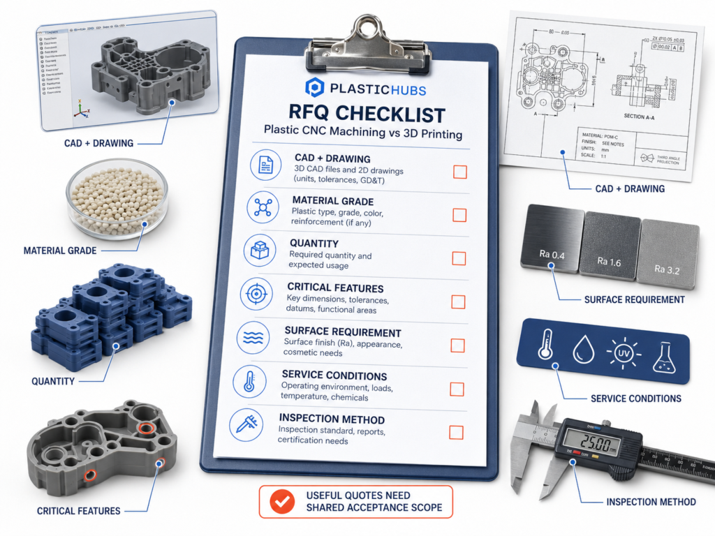
Two quotations are comparable only when both suppliers receive the same acceptance scope. Send the following information with the CAD model. Do not ask only for “CNC versus 3D-printing prices.”
| Information to provide | Decision value |
| 3D CAD and 2D drawing | Separates model geometry from datums, fits, threads, tolerances, and inspection requirements |
| Exact material grade and permitted substitutions | Prevents same-name plastics from being treated as equivalent |
| Prototype purpose and failure consequence | Shows whether the part must prove appearance, fit, load, wear, sealing, environment, or end use |
| Current quantity, later quantity, and design status | Supports setup, iteration, batch, and future-process decisions |
| Function-controlling features | Identifies where machining, compensation, inserts, or post-processing may be required |
| Surface and appearance requirements | Defines acceptable tool marks, print texture, transparency, color, and finishing |
| Service conditions | Connects temperature, chemicals, moisture, friction, load, and cycles to material selection |
| Inspection and acceptance method | Prevents a low-scope quote from appearing cheaper than a verified part |
A useful process review should return assumptions and risks as well as price. It should state the proposed material and process, DFM changes, finishing route, inspection scope, and any feature that still needs acceptance testing.
Questions That Often Change the Process Choice
Can a 3D-printed part be CNC machined afterward?
Yes, if the printed material and part design can withstand machining. The supplier should plan the print, support, workholding area, and machining allowance together. Machining an unplanned print may expose porosity, bend the part, or remove too much material.
Can transparent printed resin replace machined acrylic or polycarbonate?
Not by name alone. Transparent print resin, acrylic stock, and polycarbonate stock behave differently and respond differently to finishing. Choose by the test goal, such as appearance, optical quality, impact, or heat resistance.
What if only one bore or sealing face needs close control?
Do not apply the same requirement to the whole part. Print the geometry if it otherwise favors additive manufacturing, leave allowance at the interface, and machine and inspect that feature afterward.
Should an RFQ specify the 3D-printing process?
Specify it when the project already depends on a known material or process route. If the route is open, state the finished-part requirements and ask the supplier to identify the proposed process, material system, orientation assumptions, post-processing, and acceptance method.
When should injection molding be quoted alongside CNC and 3D printing?
Request a molding comparison when the design is stable, the expected quantity can justify tooling, and molded-part behavior is part of the requirement. Include the cost and schedule of tooling changes, sampling, and validation rather than comparing only unit prices.
PlasticHubs Process Review
PlasticHubs supports plastic CNC machining, plastic prototyping, and low-volume plastic-part projects. Send the CAD file, drawing, material grade, quantity, function-controlling features, finish, service conditions, and inspection requirements for a process and DFM review.
Review Plastic CNC Machining and Low-Volume Plastic Production, or submit your project details.